Content Source: 2019 Slingshot Owner’s Manual (9928978 REV 05) > Features and Controls Chapter

IMPORTANT

The Owner's Manual for this vehicle contains warnings, instructions and other information you must read and fully understand before safely riding or performing maintenance on this vehicle.Always follow the warnings and instructions in Owner's Manual.

Click the CONTENTS link above for the Table Of Contents, or download a full PDF of the Owner Manual in the Owner Support area of Polaris.com

Console and Switches

Image

  • Turn Signal Lever; Cruise Control Switches; Headlight High/Low Beam Switch
  • Instrument Cluster

  • Ignition Switch
  • Horn Button

Horn

Press the horn button to sound the horn. The ignition switch must be in the ON position.

Ignition Switch

The ignition key operates the ignition switch, glove box lock and storage compartment locks (behind seats). Read the engine starting procedures beginning on Starting the Engine before starting the engine. Store the spare key in a safe place separate from the main key.
Place the ignition key in the ignition switch to operate the following functions of the switch.
OFF All electrical circuits are off. Hazard signals can be activated. The key can be removed.
ON All electrical circuits are on. The ignition key cannot be removed. Headlight, taillight, running lights, turn signals, horn, radio and instrument lights are powered.
ACC Power is supplied to accessory circuits, radio, instruments and hazard signals. The key can be removed.

Headlight High/Low Beam Switch

The headlights are always on when the ignition switch is in the ON position. To switch the headlights between low beam and high beam, tap the turn signal lever forward, toward the steering wheel. The master lighting switch (Canada) must be in the ON position to allow operation of the high beam headlights. See Master Lighting Switch (Canada).

Turn Signal Lever

Before turning, activate a turn signal to alert others of your intentions. Check turn signal lamps before each ride.
NOTE
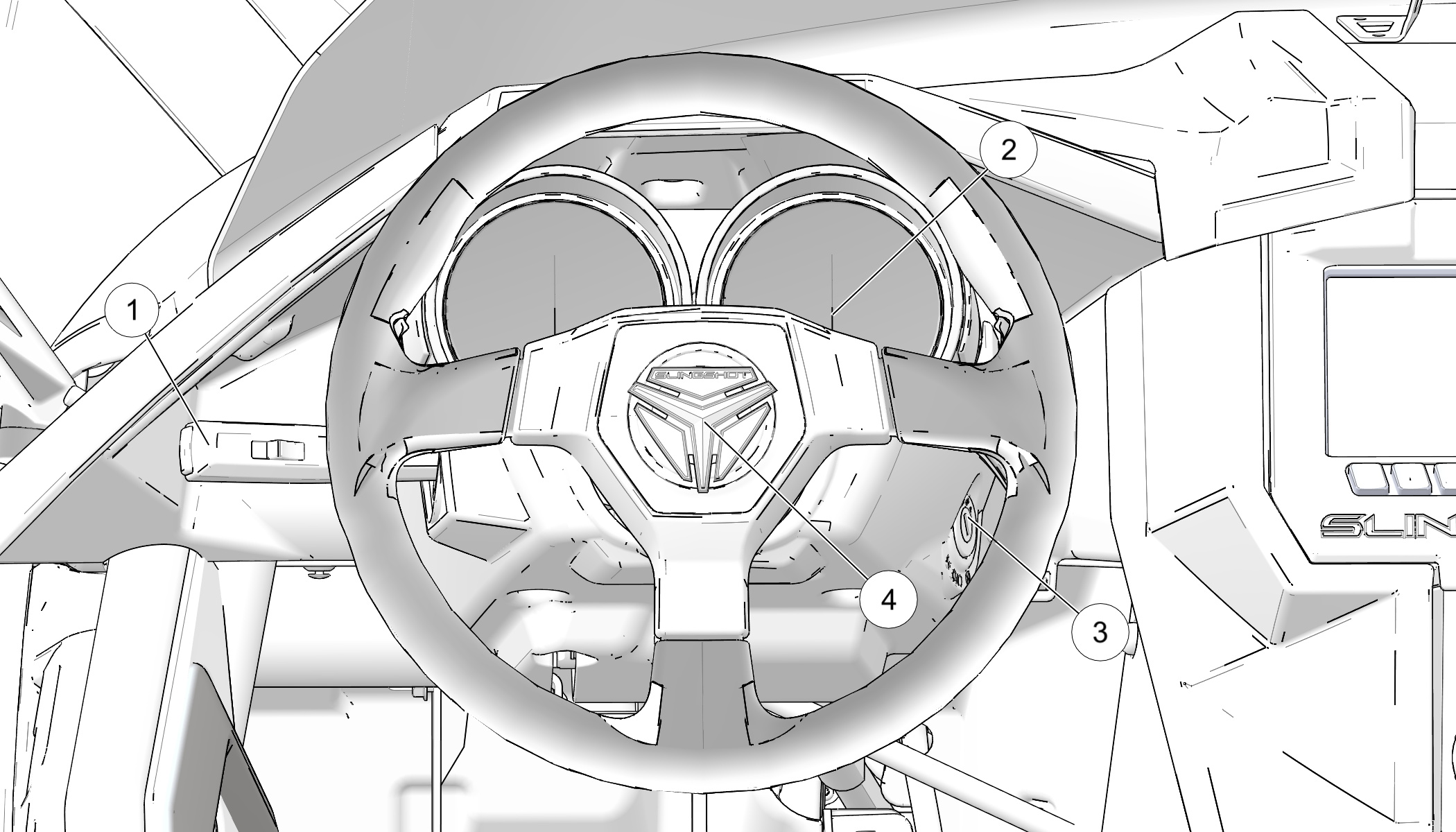
The key must be in the ON position to activate the turn signals.
  1. Move the turn signal lever downward to signal a left turn. The left turn signal lamps at the front and rear of the vehicle will flash. The indicator arrows on the console will flash when a turn signal or hazard signal is activated.
  2. Move the lever upward to signal a right turn. The right signal lamps and indicator will flash.
  3. The turn signal automatically cancels and the lever returns to the center position when the turn is completed.

Cruise Control Switches

The cruise control switch and set button are located on the turn signal lever. Before using the cruise control, read the safety and operation procedures. See Using Cruise Control.
Image

Hazard Switch/Emergency Flashers

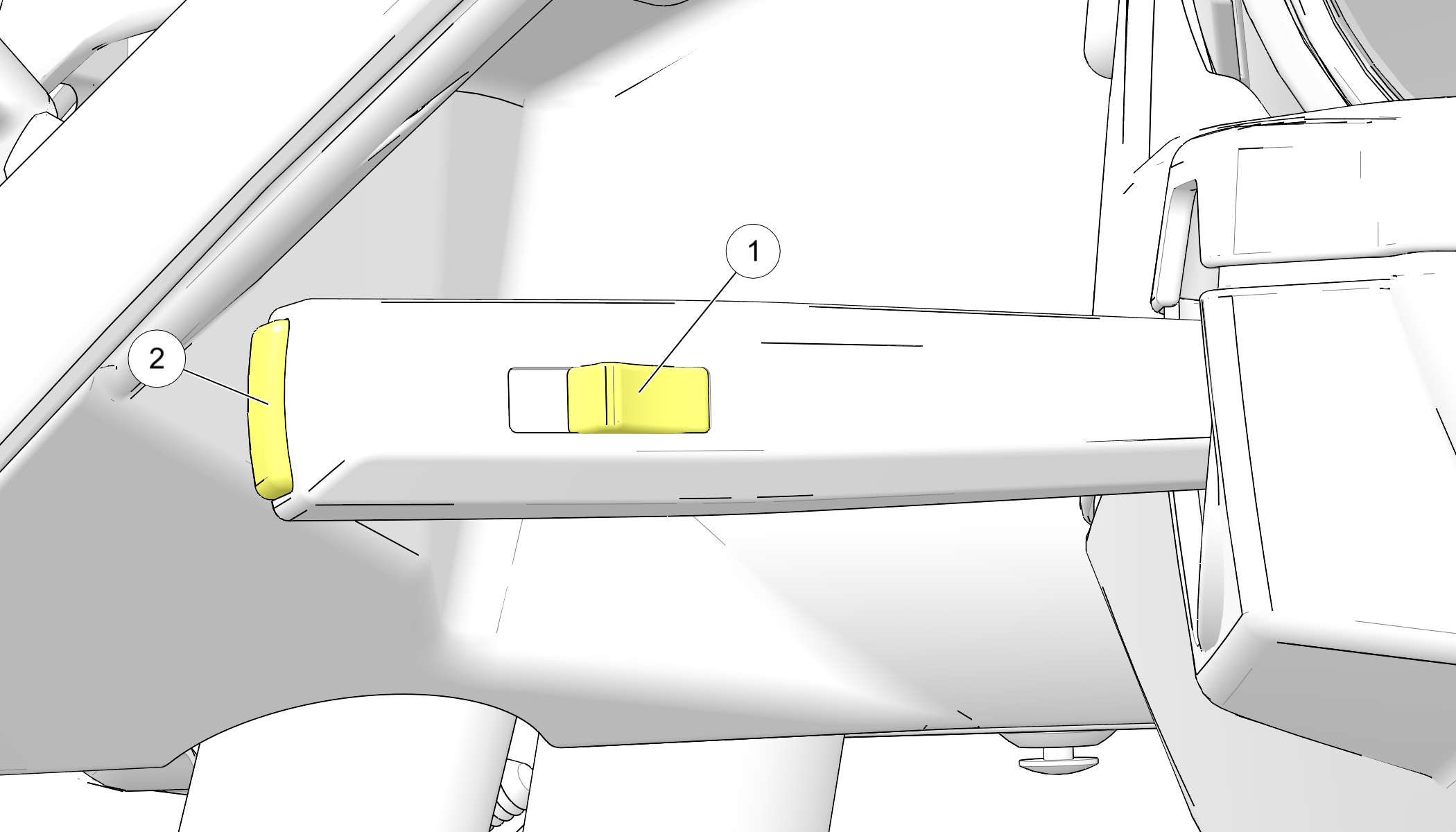
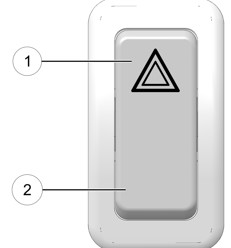
All turn signals flash when the emergency flashers are activated. Press the top of the hazard switch to turn the flashers on. Press the bottom of the switch to turn the flashers off. The ignition switch does not have to be on to activate the flashers.

Image

Master Lighting Switch (Canada)

The master lighting switch must be in the ON position to allow operation of the high beam headlights.

Image

One-Touch Starter Switch

Use the one-touch starter switch to start the engine. Read the engine starting procedures before starting the engine. See the Starting the Engine section for details.

Mode Button

The mode button is located on the dashboard near the instrument cluster.
Use the mode button to toggle through the modes of the multi-function display. See Multi-Function Display. Use the mode button to set the display units to either standard or metric units of measurement. See Display Units (Standard/Metric).

Electronic Stability Program (ESP) Switch

The ESP is active by default. This feature helps reduce the risk of accident by providing traction control and stability control. If ESP senses a loss of stability due to loss of traction (skidding) the ESP intervenes by automatically applying brakes to one or more wheels and reducing power to the rear wheel.
WARNING
No stability control, traction control or anti-lock braking system can fully protect you from every situation. Always be mindful of road conditions. Always drive safely and within the limits of the driver, vehicle and road conditions.
WARNING
Stability control, traction control and anti-lock braking systems rely on grip between the tires and the road to function properly. In a hydroplane situation, tires lose contact with the road and the effectiveness of these features may be diminished.
WARNING
Operating the vehicle under normal riding conditions with the ESP disabled could result in an increased risk of loss of vehicle control, rollover, personal injury and death.

  • The electronic stability control system does not compensate for or reduce the risks associated with:
  • excessive speed
  • reduced traction on rough, uneven or loose surfaces
  • poor judgment
  • improper operation
  • hydroplaning
  • Under certain circumstances, such as when the vehicle is stuck in a low traction situation, it may be necessary to disable the ESP temporarily. Always enable the ESP for normal operation.

Image
ESP Switch Operation
Objective Action Comments
Disable Traction Control Press and release switch Traction Control indicator illuminates in tachometer
Disable ESP (Traction Control and Stability Control) Press and hold switch for 5 seconds Traction Control indicator and ESP OFF indicator illuminate in tachometer
Enable ESP (if disabled) Press and release switch Traction Control indicator and ESP OFF indicator extinguish

© Copyright Polaris Industries Inc. All rights reserved.