Content Source: 2019 GEM em1400 LSV Owner’s Manual (9929177 R02) > Features and Controls Chapter
| IMPORTANT |
|
The Owner's Manual for this vehicle contains warnings, instructions and other information you must read and fully understand before safely riding or performing maintenance on this vehicle.Always follow the warnings and instructions in Owner's Manual. Click the CONTENTS link above for the Table Of Contents, or download a full PDF of the Owner Manual in the Owner Support area of Polaris.com |
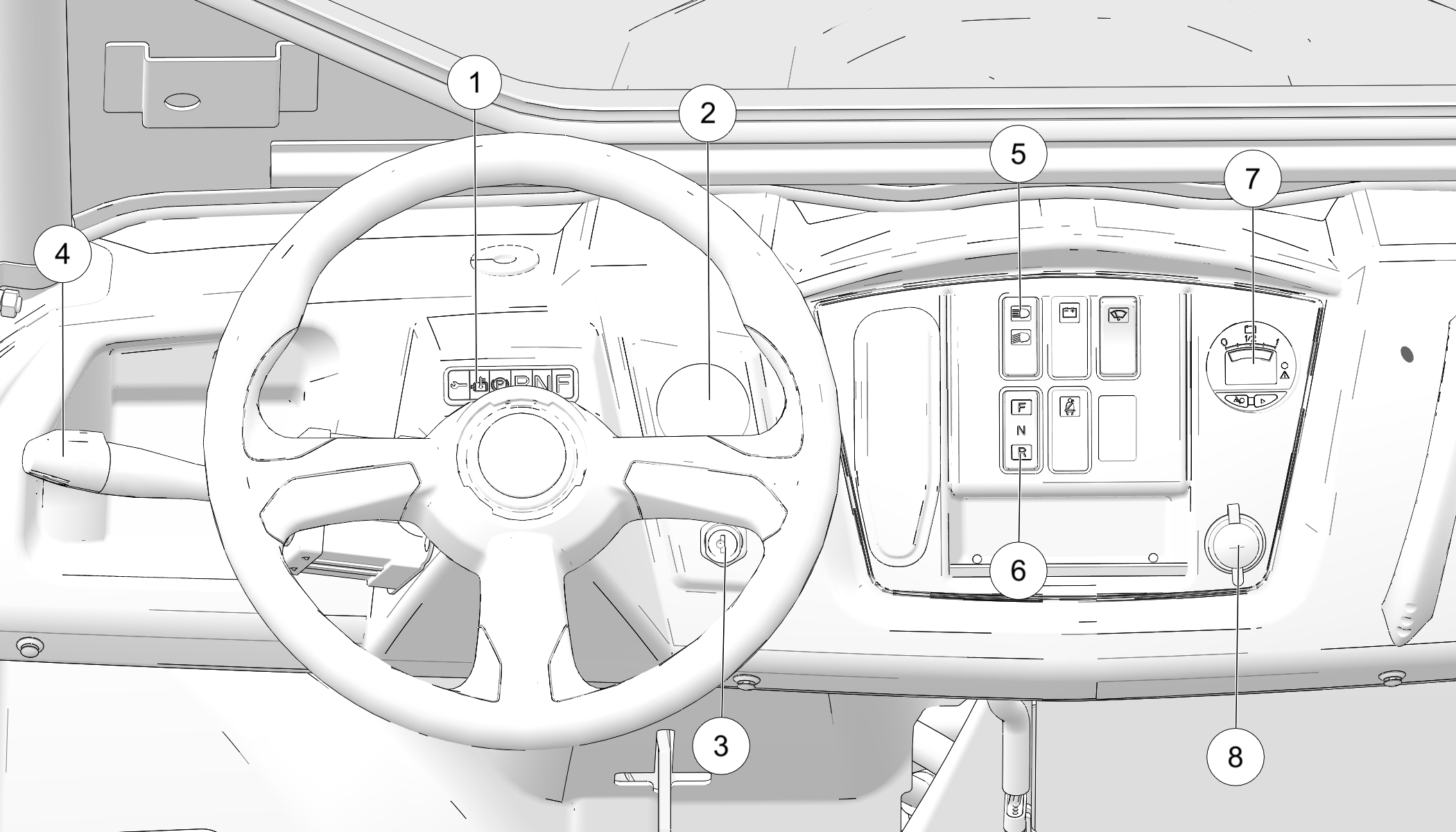
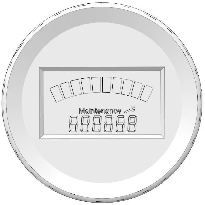
The Indicator Panel
is located above the steering wheel on the console ![]() . The indicator lights activate
when the key is in the ON position.
. The indicator lights activate
when the key is in the ON position.
|
Indicator |
Status |
Indicates |
|
|---|---|---|---|
 |
Malfunction |
Steady |
Electrical malfunction (flash sequence on controller indicates type; see troubleshooting guide on Charge Status Indicator Troubleshooting Guide) |
|
Accelerator pedal is pressed while key is being turned on (release pedal to extinguish lamp) |
|||
|
Charger is plugged in (vehicle will not operate when charging; unplug charger, wait for charge indicator to turn off before operating) |
|||
 |
Park Brake |
Steady |
Engaged park brake |
 |
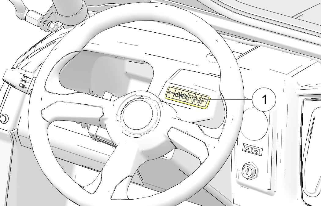
Gear Position |
Steady |
Selected gear (forward/neutral/reverse) |
 |
Motor/Controller High Temperature |
Flashing |
Reduced performance due to elevated temperature |
|
Steady |
Power delivery terminated to protect against overheating |
||
|
If either occurs, stop the vehicle and turn the key off. Allow the motor and controller to cool adequately before operating. |
|||
The speedometer displays vehicle speed in miles per hour (MPH).
| Never turn the key to the OFF position while the vehicle is in motion. This could lead to loss of speed control and loss of vehicle control, which could result in serious injury or death. |
| TIP |
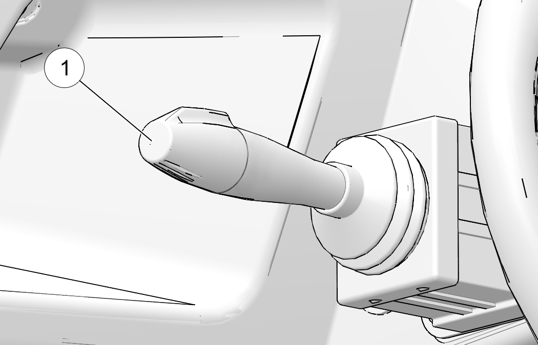
| The key must be in the ON position to activate the turn signals. |
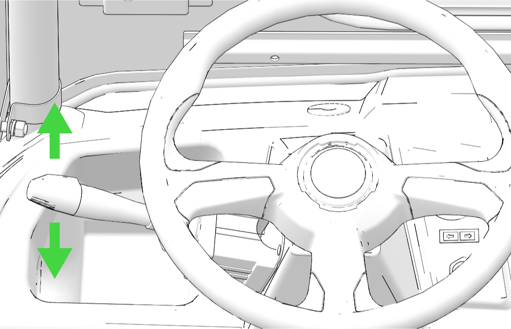
Move the turn signal
upward to signal a right turn. The right signal lamp and indicator
will flash.
Move the turn signal
lever downward to signal a left turn. The left turn signal lamp below
the front headlight will flash.
The left turn indicator on the dash will also flash.
Return the lever to the center position
to end the signal. If the operator does not end the signal within
45 seconds, an alert
will sound.
The corresponding turn signal indicator flashes on the dash when a signal is activated.
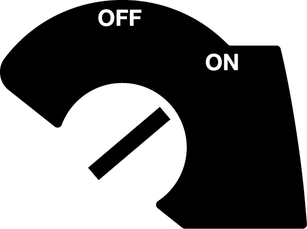
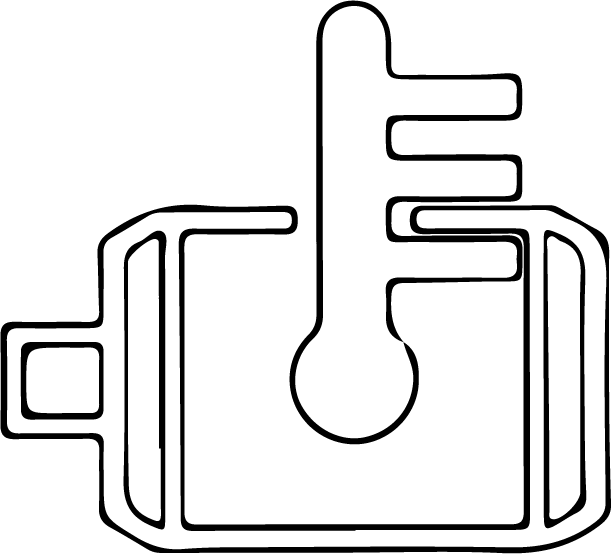
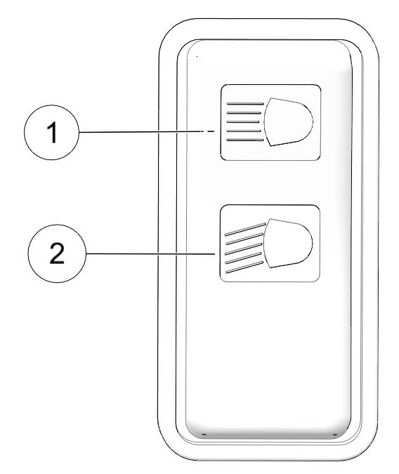
The ignition switch
key must be in the ON/RUN position to operate the headlights. Press
the top of the rocker switch ![]() toward
the dash to place the headlights on high beam. Move the rocker switch
to the center position
toward
the dash to place the headlights on high beam. Move the rocker switch
to the center position ![]() to place the headlights on low
beam. Press the bottom of the rocker switch to turn off the headlights.
to place the headlights on low
beam. Press the bottom of the rocker switch to turn off the headlights.
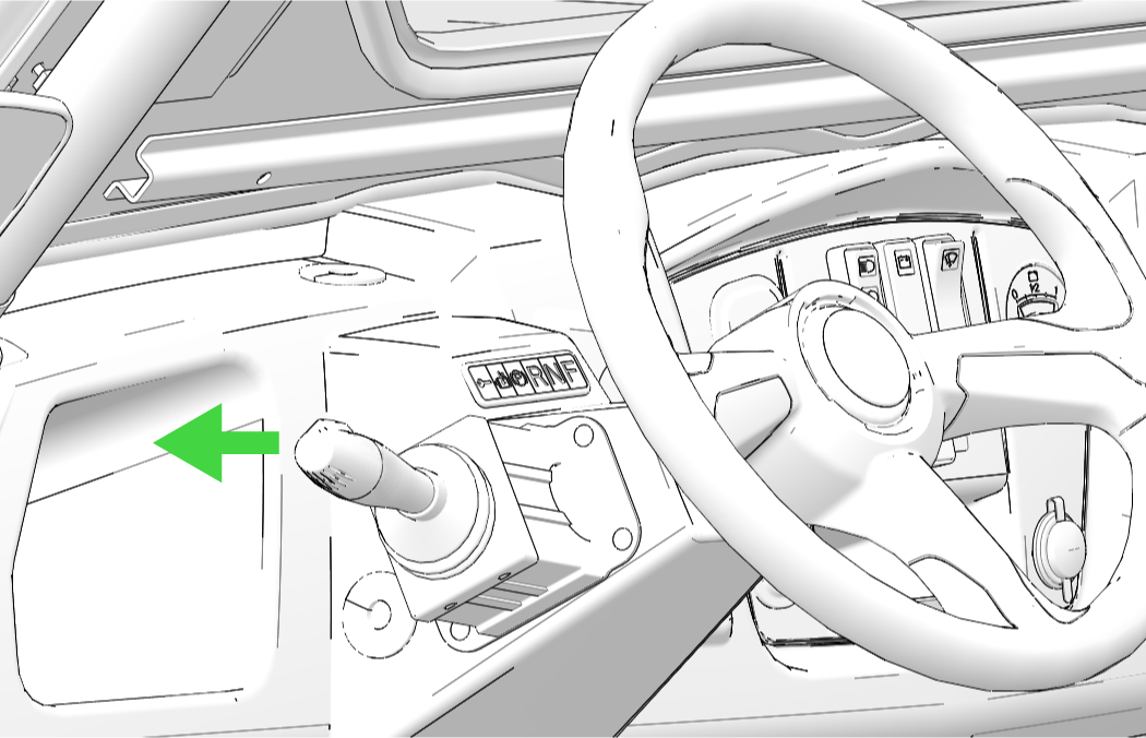
| TIP |
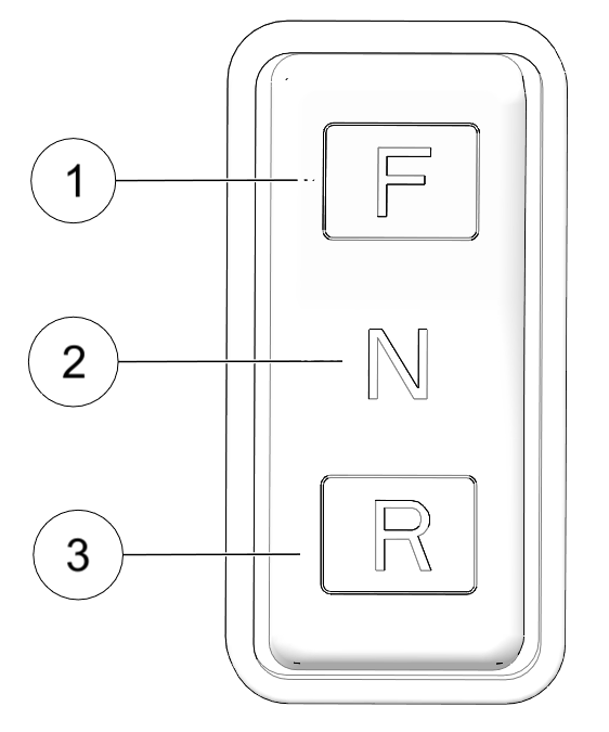
| The malfunction light will illuminate after reversing direction if you press the accelerator pedal before coming to a complete stop. |
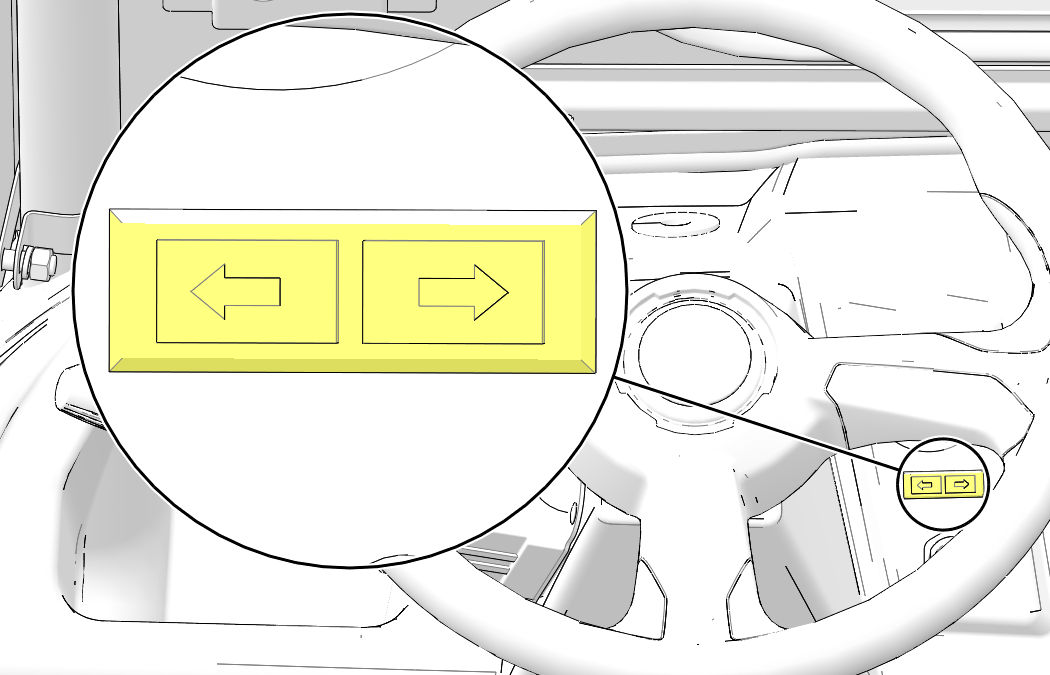
Always come to a complete
stop before reversing direction. To choose the forward option, push
the top of the switch ![]() . Push the bottom of the switch
to choose reverse operation
. Push the bottom of the switch
to choose reverse operation ![]() . When
the direction selector is in the center position
. When
the direction selector is in the center position ![]() , the vehicle is in neutral.
The vehicle will not move if the accelerator is depressed.
, the vehicle is in neutral.
The vehicle will not move if the accelerator is depressed.
| caution |
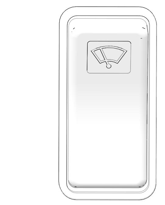
| A worn or damaged wiper blade could impair operator vision and result in an accident. A worn wiper blade could also damage windshield glass. Always replace worn or damaged wiper blades promptly. |
The windshield wiper switch is located on the dash. Press the top of the switch to turn the wiper on. Press the bottom of the switch to turn the wiper off. If the wiper fails to work, check for a blown fuse at the in-line fuse block. See the Fuses and Relays section of your owner’s manual for more information on fuses.
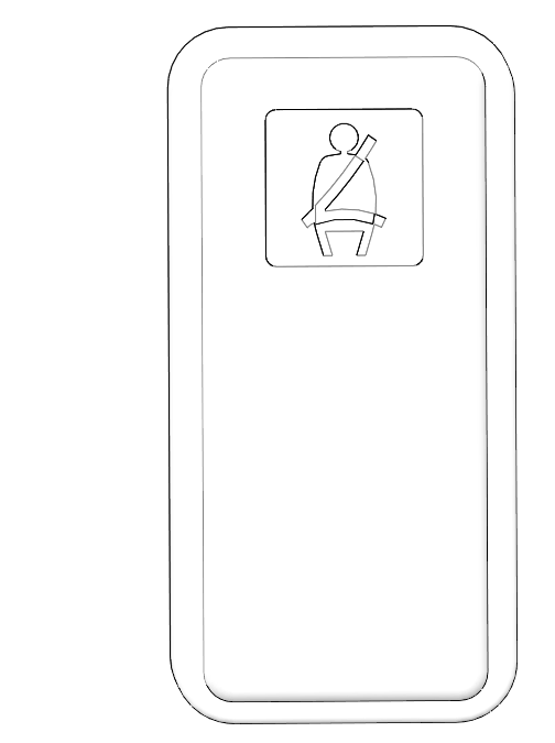
When the key is turned to the ON position, the seat belt warning lamp will flash if the driver’s seat belt is not fastened. The lamp is a reminder to wear the appropriate protective apparel, and to fasten the seat belts before operating.
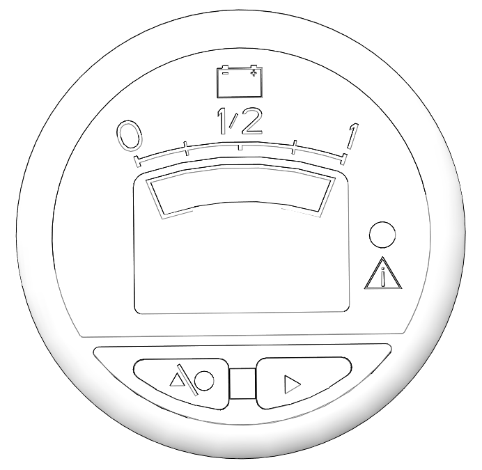
The battery discharge
indicator ![]() displays the amount of charge removed (used) from fully charged batteries. When the batteries are
fully charged, the gauge will display 100%. The charge status indicator
will be solid green. Avoid
discharging the batteries more than 80%.
displays the amount of charge removed (used) from fully charged batteries. When the batteries are
fully charged, the gauge will display 100%. The charge status indicator
will be solid green. Avoid
discharging the batteries more than 80%.
To help prevent the
vehicle from rolling, set the park brake ![]() when parking the vehicle. When
the park brake is set and the park brake indicator is illuminated,
motor speed is limited.
If the accelerator is applied, this limiting feature
prevents operation, which protects the park brake pads from excessive
wear.
when parking the vehicle. When
the park brake is set and the park brake indicator is illuminated,
motor speed is limited.
If the accelerator is applied, this limiting feature
prevents operation, which protects the park brake pads from excessive
wear.
Always
apply the service brakes before engaging or releasing the park brake.
| TIP |
| This feature will not operate properly if the park brake connector or switch (under the hood) malfunctions or becomes disconnected, or if the switch has moved. Check for disconnection, then see your dealer promptly if this feature fails to operate properly. |
|
Color |
Indication |
Code Definition |
|---|---|---|
|
Green |
Solid |
Charge is complete, charger is in maintenance mode. |
|
Green |
Fast Flash |
Less than 80% of charge is completed. |
|
Green |
Slow Flash |
More than 80% of charge is completed. |
|
Amber |
Flashing |
Power mode is reduced, low AC voltage or high internal charger temperature exists; remove seat to improve air flow. |
|
Red |
Flashing |
Charger error exists; reset charger power and refer to Troubleshooting Guide on Charge Status Indicator Troubleshooting Guide. |
The 12-volt receptacle can be used to power accessories, but is limited to 10 amps (the terminal board and 12-volt outlet are fused together at 10 amps.

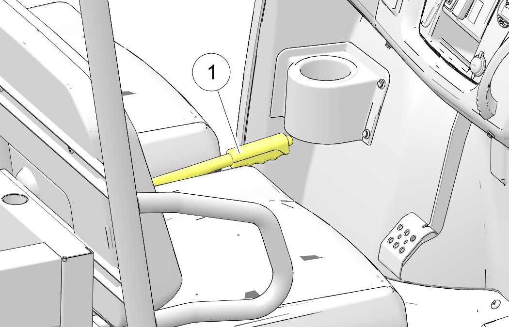
Press the turn signal
wand inward toward the instrument pod ![]() to
sound the horn.
to
sound the horn.
Push the turn signal lever forward to cause all turn signal lamps to flash simultaneously. Use this feature to alert others of an emergency or other situation requiring caution, especially if your vehicle becomes disabled on or near a road. Pull the turn signal lever rearward to cancel the hazard signals.
© Copyright Polaris Industries Inc. All rights reserved.