
Content Source: 2020 PRO XD Gas Owner’s Manual (9939921 Rev 01) > Features and Controls Chapter
| IMPORTANT |
|
The Owner's Manual for this vehicle contains warnings, instructions and other information you must read and fully understand before safely riding or performing maintenance on this vehicle.Always follow the warnings and instructions in Owner's Manual. Click the CONTENTS link above for the Table Of Contents, or download a full PDF of the Owner Manual in the Owner Support area of Polaris.com |
| NOTICE |
|
The use of a high pressure washer may damage the instrument
cluster. Wash the vehicle by hand or with a garden hose using
mild soap. Do not use
alcohol to clean the instrument cluster. Do not allow insect sprays
to contact the lens. Immediately
clean off any gasoline
that splashes on the instrument cluster.
|
|
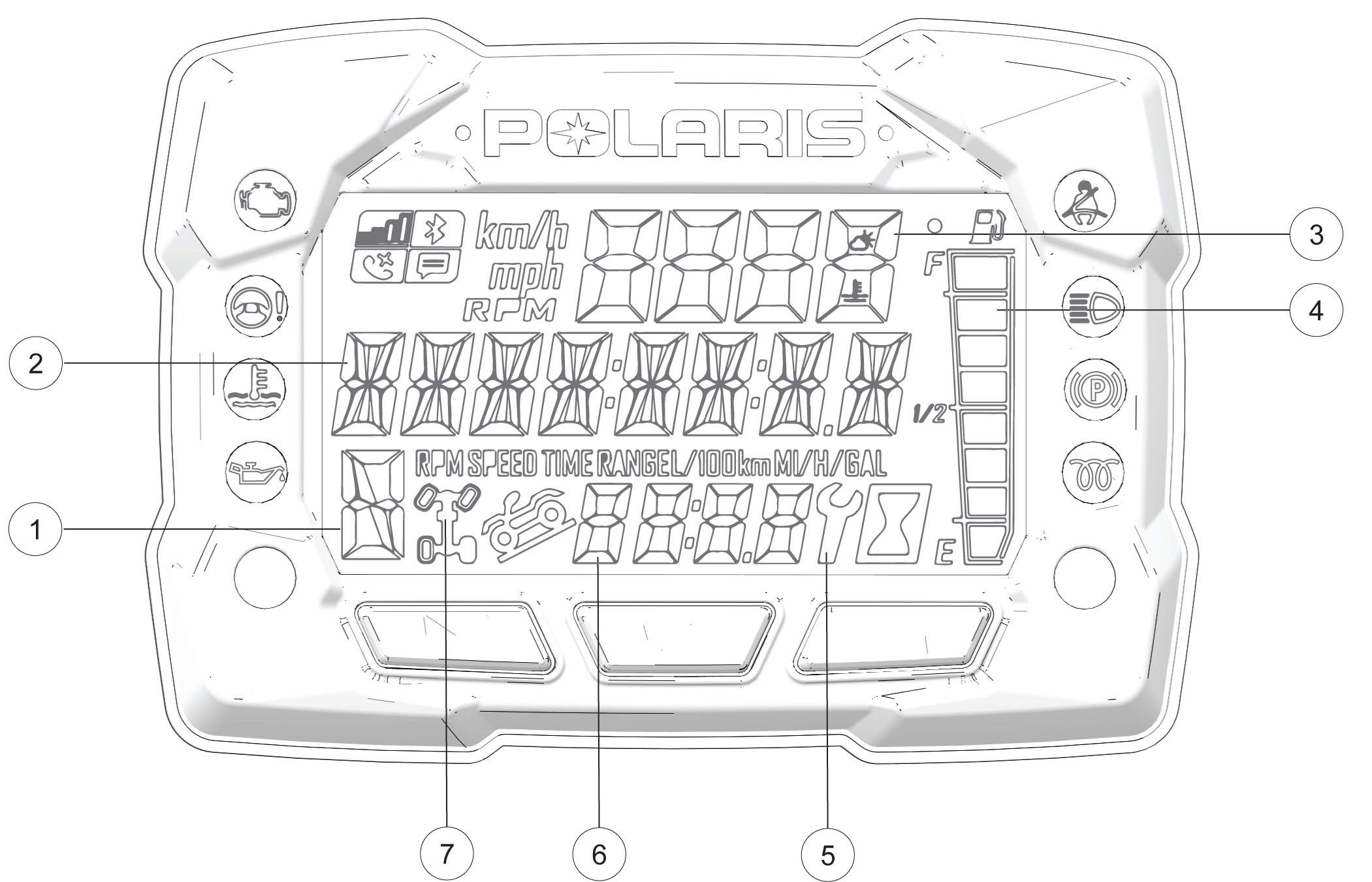
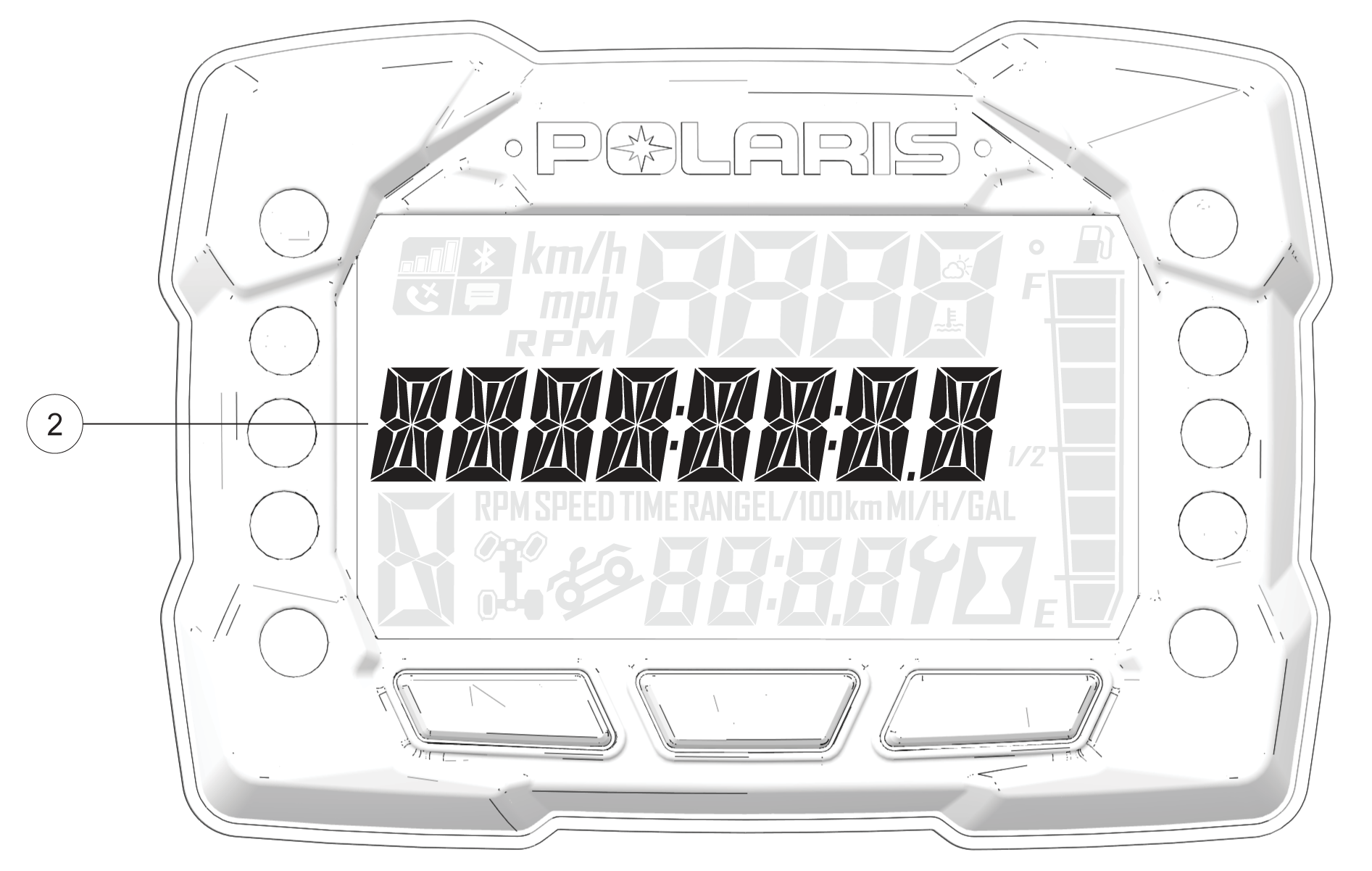
H = High Gear L = Low Gear N = Neutral R = Reverse Gear P = Park -- = Gear Signal Error (or shifter between gears) |
|
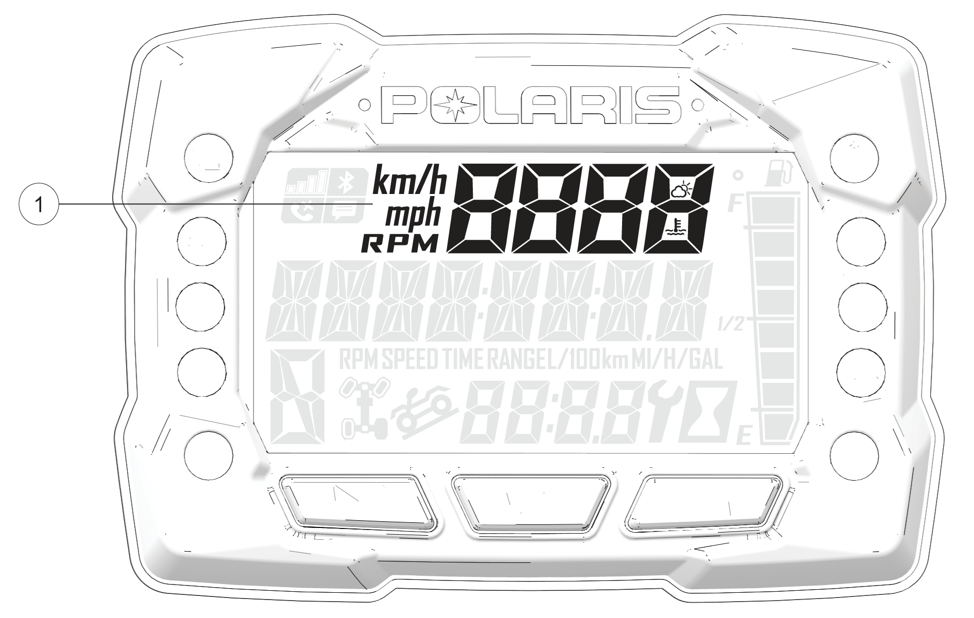
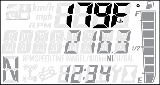
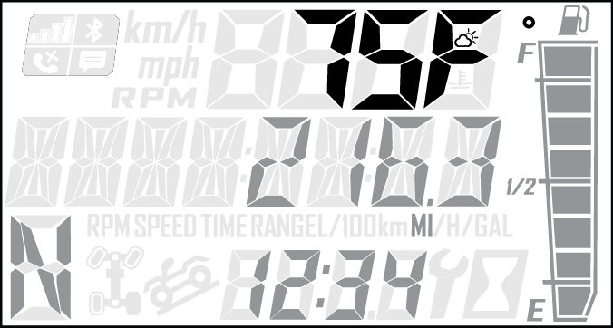
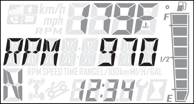
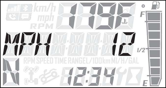
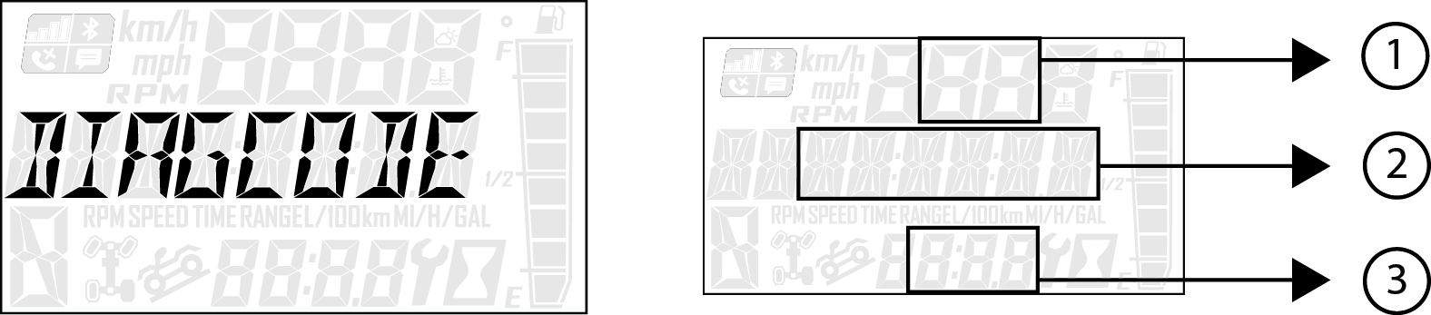
| This area displays odometer, trip meter, trip meter 2, voltage, engine temperature, engine hour meter, programmable service hour interval, ground speed, or engine RPM. | |
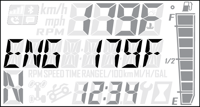
| This area displays engine RPM, ground speed, or coolant temperature. | |
| The segments of the fuel gauge show the level of fuel in the fuel tank. When the last segment clears, a low fuel warning is activated. All segments including the fuel icon will flash. Refuel immediately. | |
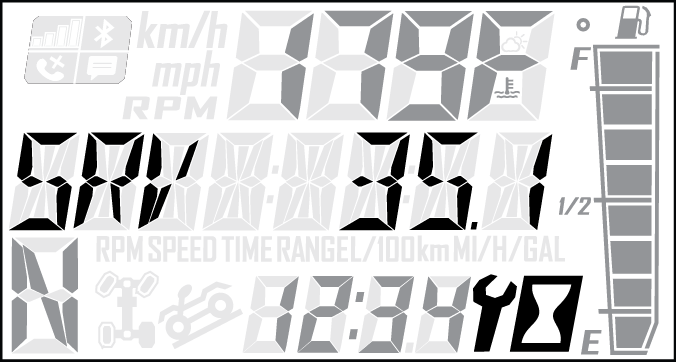
| A flashing wrench symbol alerts the operator that the preset service interval has been reached. Your POLARIS dealer can provide scheduled maintenance. See Service Hours for more information. | |
| The clock displays time in a 12-hour or 24-hour format. | |
| Segments of the indicator illuminate based on drive mode engaged. |
|
|
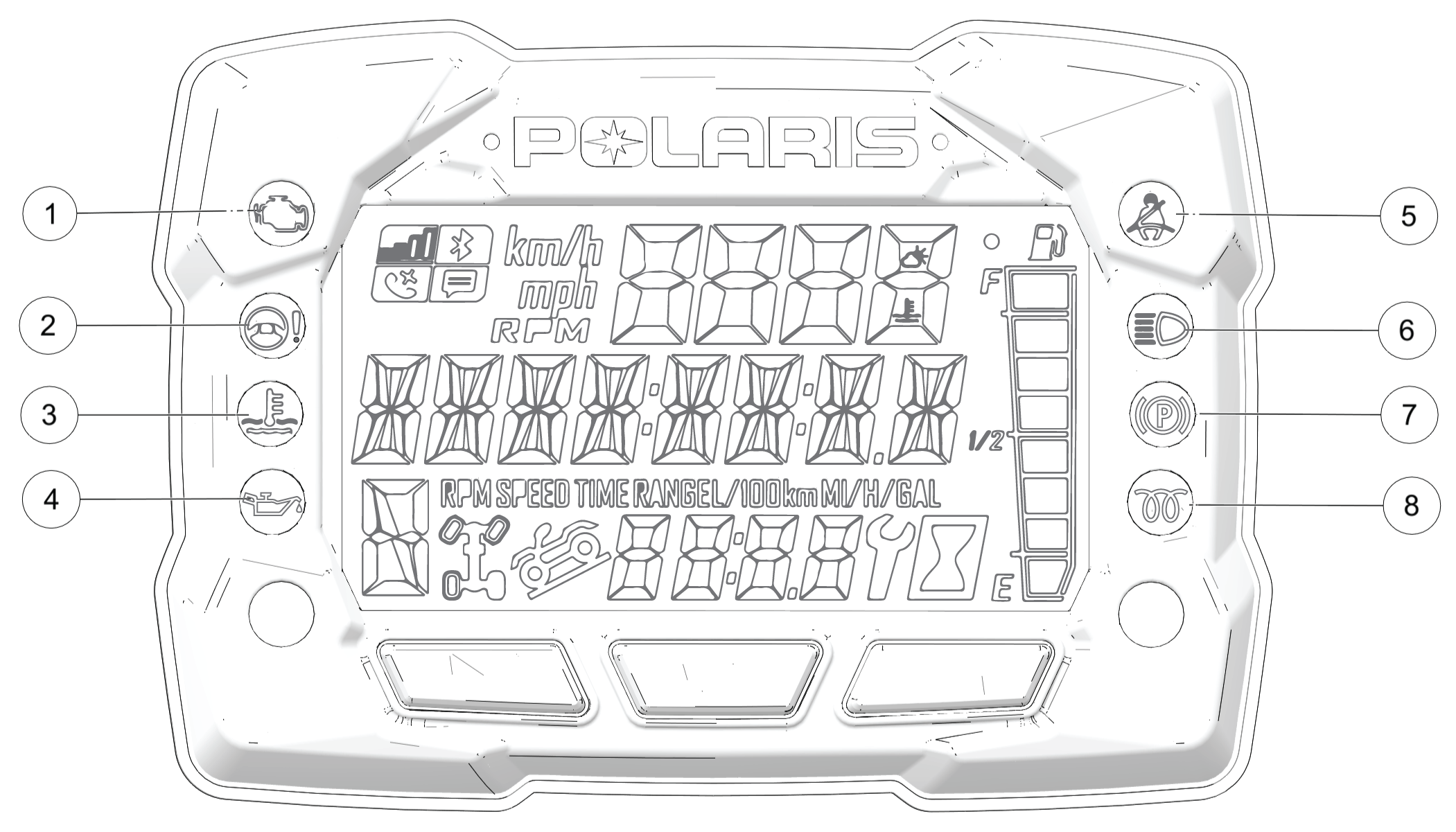
This lamp illuminates when the ECM detects a Diagnostic Trouble Code in the engine management system. Do not operate the vehicle if this warning appears. Serious engine damage could result. Your authorized POLARIS dealer can assist. This lamp will also illuminate if the vehicle is keyed on but not started; it will turn off once the vehicle is started. | |
|
|
This lamp illuminates to indicate that EPS has shut down. EPS shuts down automatically 5 minutes after the engine is turned off if the key remains in the ON position. Turn the key off and on to reset the unit. If the light remains on after starting the engine, the EPS system is inoperative. Your POLARIS dealer can assist. | |
|
|
This lamp illuminates to indicate an overheated engine. If the indicator flashes, a severe overheating condition exists and the engine will shut down automatically. The vehicle will not start again until the engine has sufficiently cooled down. Whenever this lamp illuminates, the engine load should be reduced in any way possible to avoid overheating and shutting down the engine. | |
|
|
This lamp illuminates if engine oil pressure drops below safe operating pressure. If this lamp illuminates while the engine is running, turn the engine off as soon as safely possible and check the oil level. If the oil level is correct and the lamp remains on after the engine is restarted, turn the engine off immediately. | |
|
|
This lamp flashes for several seconds when the key is turned to the ON position. The lamp will keep flashing as long as riders’ seat belts are not connected. | |
|
|
This lamp illuminates when the headlamp switch is set to high beam. | |
|
|
Not used on this vehicle. | |
|
|
Not used on this vehicle. |
Speed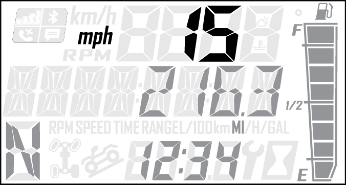
RPM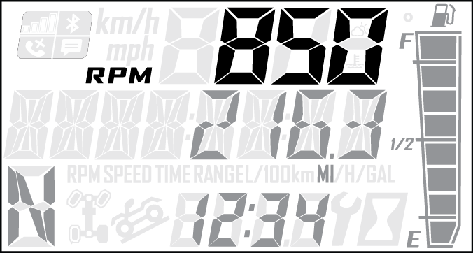
Odometer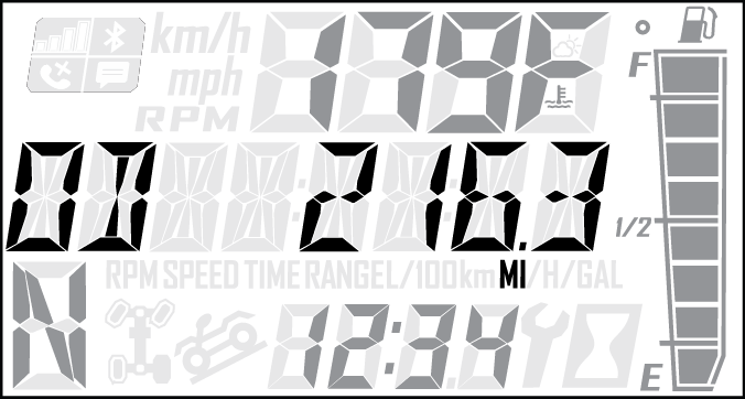
Trip 1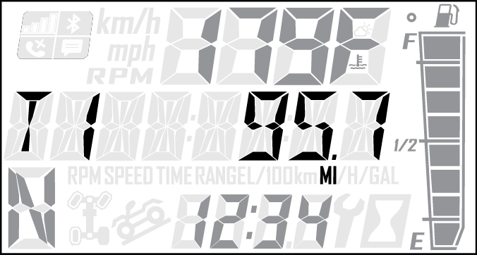
Trip 2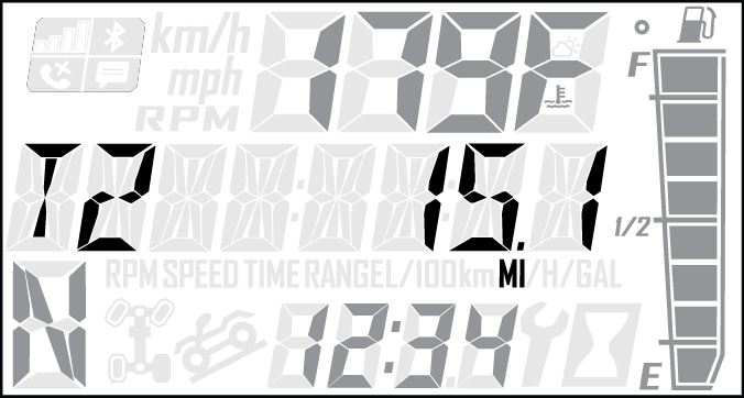
Voltage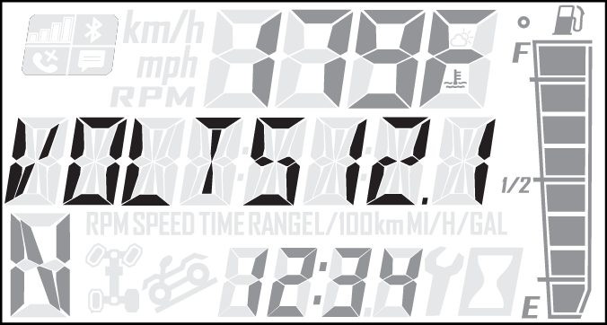
Engine Hours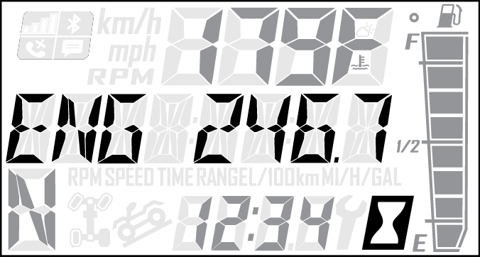
| Options Menu | Notes |
|---|---|
| Diagnostic Codes |
Only displays if fault codes are present or stored |
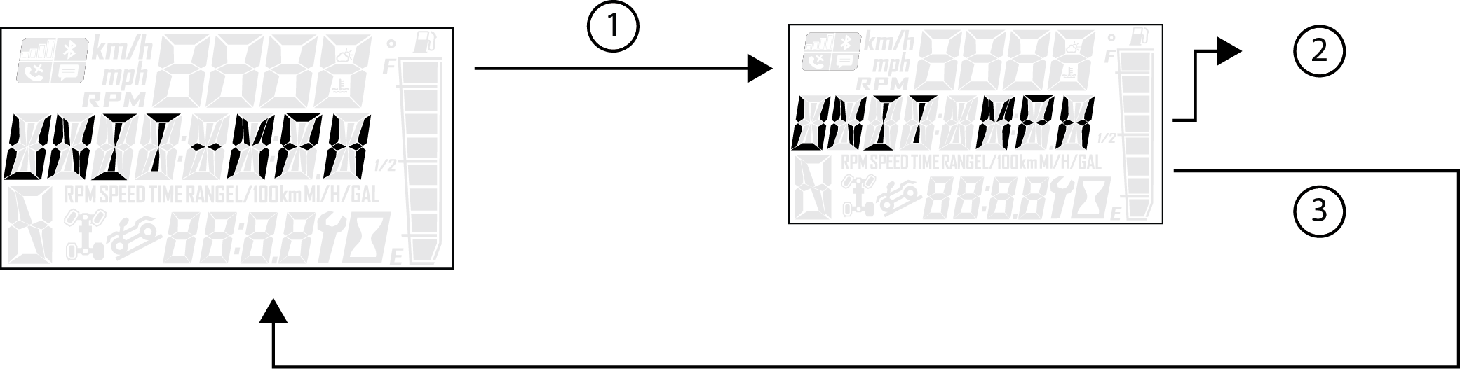
| Units - Distance |
Select MPH or KPH |
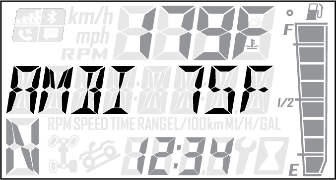
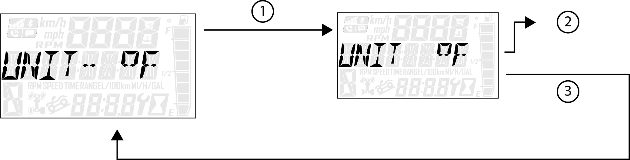
| Units - Temp |
Select between °F and °C |
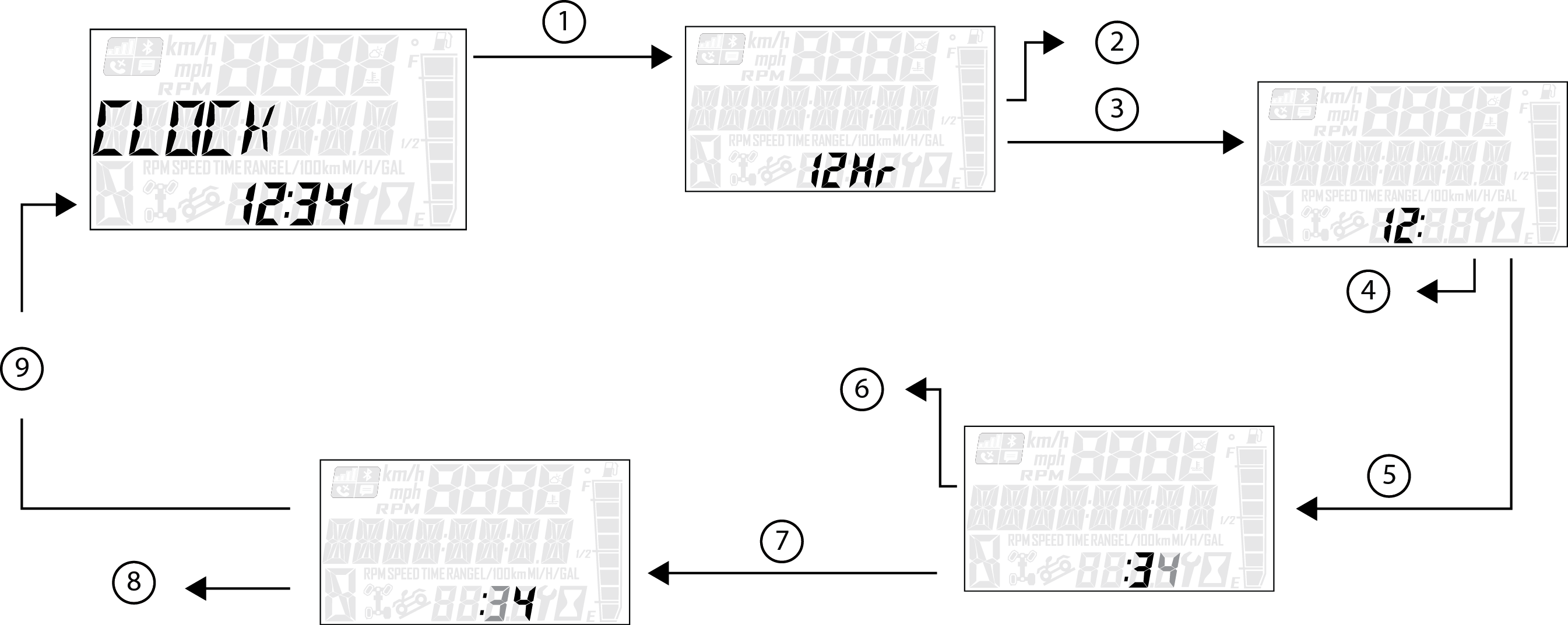
| Clock |
Select between 12H or 24H, and set time |
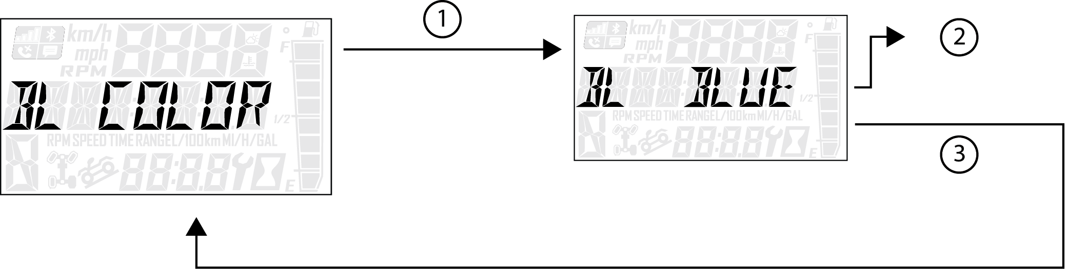
| Backlight Color |
Select between Blue or Red |
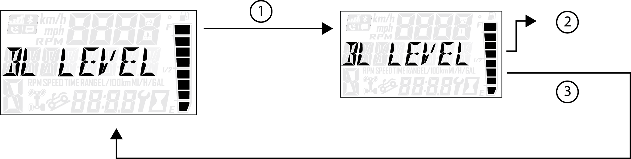
| Backlight Level |
Set backlight brightness level |
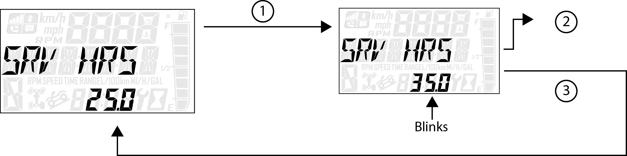
| Service Hours |
View/Set Service hours |
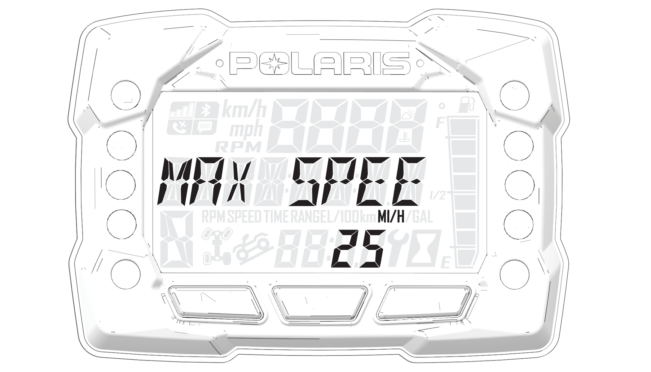
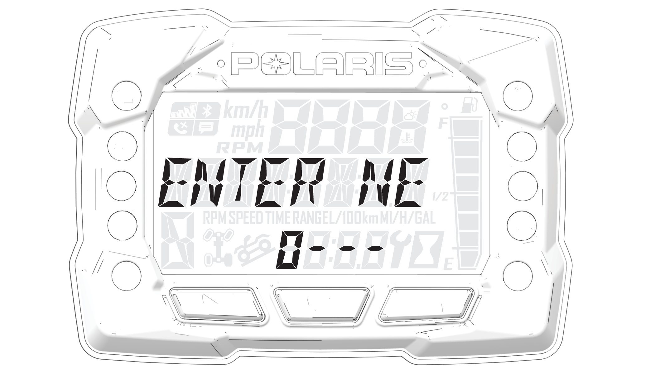
| Speed Limiting(if equipped) |
Set max speed |
| Exit Menu |
Exit |
| NOTICE |
|
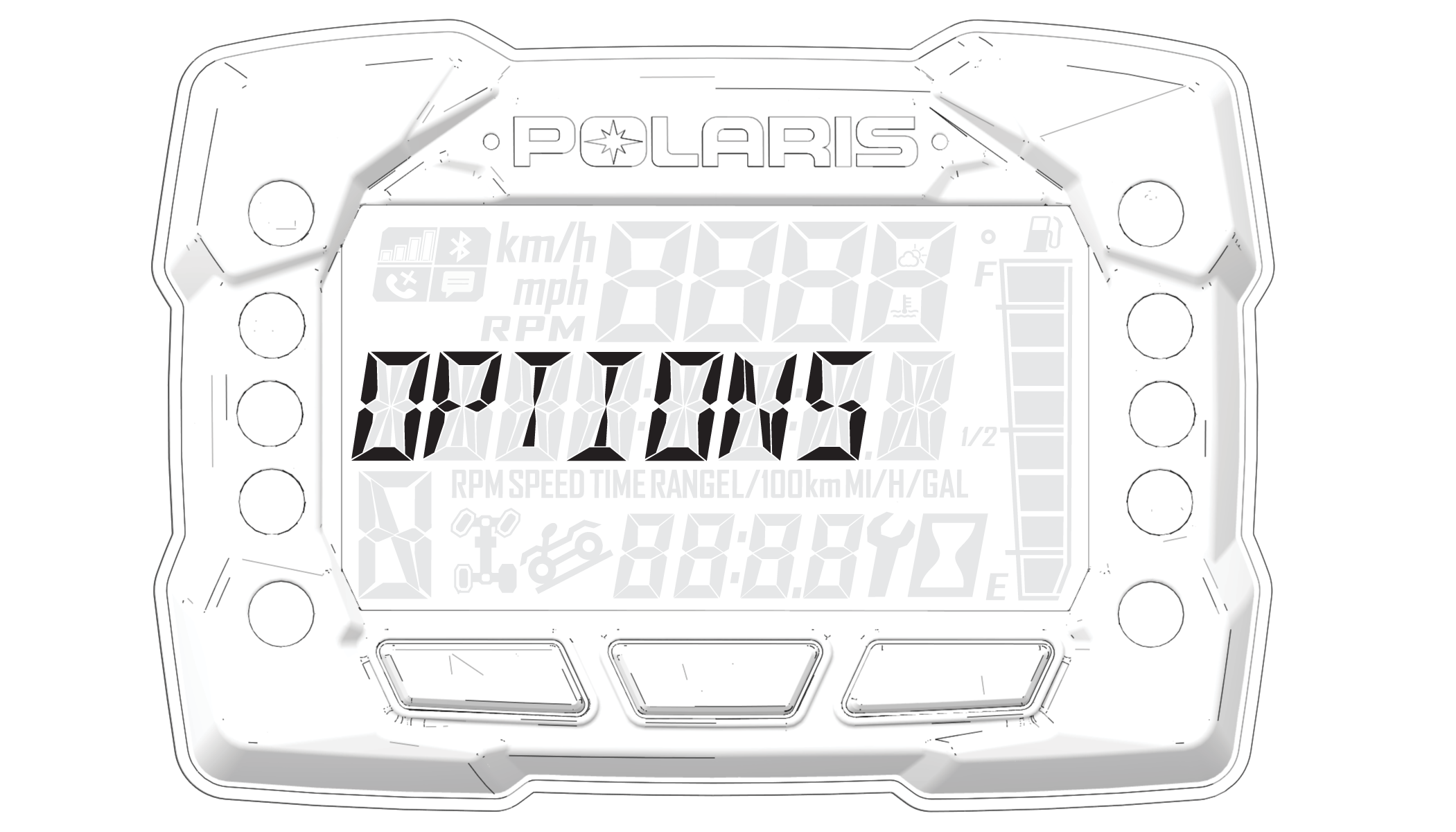
“OPTIONS” will display on the screen for 3 seconds before showing first menu item. |
Reference the image shown above:
| NOTICE |
|
“OPTIONS” will display on the screen for 3 seconds before showing first menu item. |
Reference the image shown above:
| NOTICE |
|
“OPTIONS” will display on the screen for 3 seconds before
showing first menu item. |
Reference the image shown above:
| NOTICE |
|
“OPTIONS” will display on the screen for 3 seconds before showing first menu item. |
Reference the image shown above:
| NOTICE |
|
“OPTIONS” will display on the screen for 3 seconds before showing first menu item. |
Reference the image shown above:
| NOTICE |
|
“OPTIONS” will display on the screen for 3 seconds before showing first menu item. |
Reference the image shown above:
| NOTICE |
|
To reset service hours after they have counted down to "0.0", reselect the existing setpoint or select a new service hour value. |
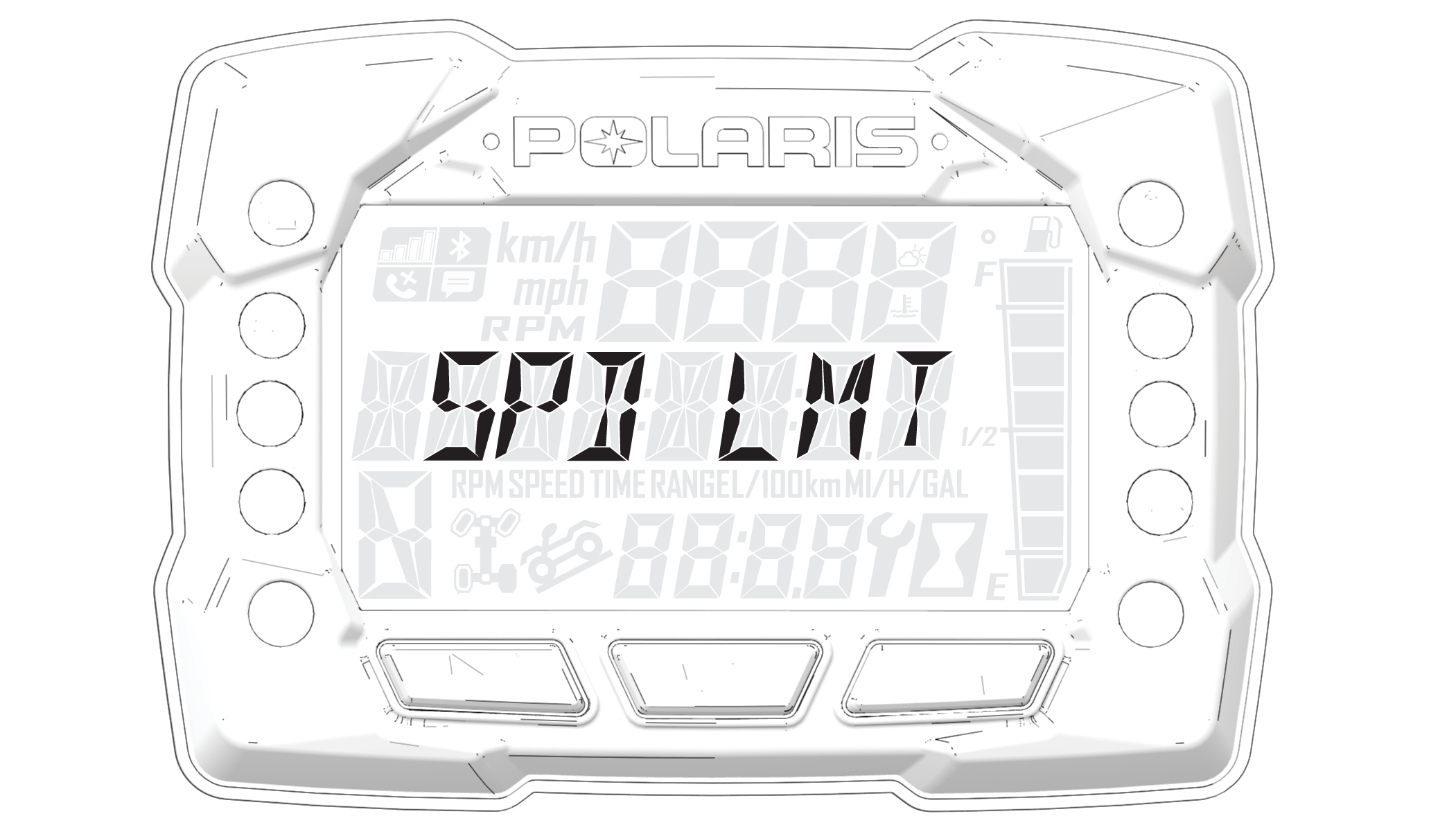
| NOTE |
| Vehicles with Adjustable Speed Limiting equipped come with the max speed set at 25 mph (40 km/h) by default. |
| Speeds of 30 mph (48 km/h) and above require the use of a DOT-approved helmet. See Personal Protective Equipment for more information. |
| NOTICE |
|
Diagnostic Code Screen will show available MIL that has
come on during that ignition cycle. |
| NOTICE |
|
“OPTIONS” will display on the screen for 3 seconds before showing first menu item. |
Toggle the Up/Down Buttons to cycle through Code(s).
| NOTICE |
|
This option will only be available if a fault code was set or is active during the current ignition key 'on' cycle. Turning off the ignition will clear any save fault codes from the gauge. |
Reference the image shown above:
|
Diagnostic Codes |
|||
|---|---|---|---|
|
Component |
Condition |
SPN |
FMI |
|
Throttle Position Sensor |
Voltage Too High |
51 |
3 |
|
Voltage Too Low |
51 |
4 |
|
|
Engine Temperature Sensor |
Voltage Too High |
110 |
3 |
|
Voltage Too Low |
110 |
4 |
|
|
Temperature Too High |
110 |
16 |
|
|
Engine Overheat Shutdown |
110 |
0 |
|
|
Intake Air Temperature Sensor |
Voltage Too High |
105 |
3 |
|
Voltage Too Low |
105 |
4 |
|
|
Manifold Absolute Pressure Sensor |
Voltage Too High |
102 |
3 |
|
Voltage Too Low |
102 |
4 |
|
|
Signal Out of Range |
102 |
2 |
|
|
Crankshaft Position Sensor |
Circuit Fault |
636 |
8 |
|
Plausibility Fault |
636 |
2 |
|
|
Vehicle Speed Signal |
Speed Too High |
84 |
8 |
|
Plausibility Fault |
84 |
2 |
|
|
Gear Sensor Signal |
Voltage Too Low |
523 |
4 |
|
Voltage Too Low |
523 |
3 |
|
|
Signal Fault |
523 |
2 |
|
|
Injector 1 (MAG) (SDI Part Load) |
Driver Circuit Open/Grounded |
651 |
5 |
|
Driver Circuit Short to B+ |
651 |
3 |
|
|
Driver Circuit Grounded |
651 |
4 |
|
|
Injector 2 (PTO) (SDI Part Load) |
Driver Circuit Open/Grounded |
652 |
5 |
|
Driver Circuit Short to B+ |
652 |
3 |
|
|
Driver Circuit Grounded |
652 |
4 |
|
|
Ignition Coil Primary Driver 1 (MAG) |
Driver Circuit Short to B+ |
1268 |
3 |
|
Ignition Coil Primary Driver 2 (PTO) |
Driver Circuit Short to B+ |
1269 |
3 |
|
Fuel Pump Driver Circuit |
Driver Circuit Open/Grounded |
1347 |
5 |
|
Driver Circuit Short to B+ |
1347 |
3 |
|
|
Driver Circuit Grounded |
1347 |
4 |
|
|
Fan Relay Driver Circuit |
Driver Circuit Open/Grounded |
1071 |
5 |
|
Driver Circuit Short to B+ |
1071 |
3 |
|
|
Driver Circuit Grounded |
1071 |
4 |
|
|
Idle Air Control |
Driver Circuit Open/Grounded |
634 |
5 |
|
Driver Circuit Short to B+ |
634 |
3 |
|
|
Driver Circuit Grounded |
634 |
4 |
|
|
Position Out of Range |
634 |
7 |
|
|
Starter Enable Circuit |
Driver Circuit Open/Grounded |
1321 |
5 |
|
Driver Circuit Short to B+ |
1321 |
3 |
|
|
Driver Circuit Grounded |
1321 |
4 |
|
|
Chassis Relay |
Driver Circuit Open/Grounded |
520208 |
5 |
|
Driver Circuit Short to B+ |
520208 |
3 |
|
|
Driver Circuit Grounded |
520208 |
4 |
|
|
All Wheel Drive Control |
Driver Circuit Open/Grounded |
520207 |
5 |
|
Driver Circuit Short to B+ |
520207 |
3 |
|
|
Driver Circuit Grounded |
520207 |
4 |
|
|
System Power |
Voltage Too High |
168 |
3 |
|
Voltage Too Low |
168 |
4 |
|
|
Throttle Safety Signal |
Voltage Too High |
520194 |
3 |
|
Voltage Too Low |
520194 |
4 |
|
|
Signal Out of Range |
520194 |
2 |
|
|
Throttle Stuck |
520194 |
7 |
|
|
Active Descent Control System |
Driver Circuit Open/Grounded |
520203 |
5 |
|
Driver Circuit Short to B+ |
520203 |
3 |
|
|
Driver Circuit Grounded |
520203 |
4 |
|
|
Idle Speed |
Speed Too High |
520211 |
3 |
|
Speed Too Low |
520211 |
4 |
|
|
Right Hand Control |
Momentary Driveline Mode Switch Press |
520468 |
31 |
|
Diagnostic Codes |
|||
|---|---|---|---|
|
Component |
Condition |
SPN |
FMI |
|
EPS Models Only |
|||
|
Vehicle Speed Sensor |
Data Valid But Above Normal Operational Range - Most Severe Level |
84 |
0 |
|
Data Erratic, Intermittent Or Incorrect |
84 |
2 |
|
|
Abnormal Rate Of Change |
84 |
10 |
|
|
Received Network Data In Error |
84 |
19 |
|
|
System Power |
Data Valid But Above Normal Operational Range - Most Severe Level |
168 |
0 |
|
Voltage Above Normal, Or Shorted To High Source |
168 |
3 |
|
|
Voltage Below Normal, Or Shorted To Low Source |
168 |
4 |
|
|
Engine Speed |
Data Valid But Above Normal Operational Range - Most Severe Level |
190 |
0 |
|
Data Erratic, Intermittent Or Incorrect |
190 |
2 |
|
|
Received Network Data In Error |
190 |
19 |
|
|
ECU Memory |
Bad Intelligent Device Or Component |
628 |
12 |
|
Out Of Calibration |
628 |
13 |
|
|
Calibration |
Out Of Calibration |
630 |
13 |
|
Steering Over Current Shut Down |
Current Above Normal Or Grounded Circuit |
520221 |
6 |
|
Steering Excessive Current Error |
Current Above Normal Or Grounded Circuit |
520222 |
6 |
|
Steering Torque Partial Failure |
Condition Exists |
520223 |
31 |
|
Steering Torque Full Failure |
Condition Exists |
520224 |
31 |
|
EPAS Inverter Temperature |
Data Valid But Above Normal Operational Range - Most Severe Level |
520225 |
0 |
|
Data Valid But Above Normal Operating Range - Moderately Severe Level |
520225 |
16 |
|
|
EPAS Communications Receive Data Error |
Data Erratic, Intermittent Or Incorrect |
520226 |
2 |
|
Condition Exists |
520226 |
31 |
|
|
Position Encoder Error |
Root Cause Not Known |
520228 |
11 |
|
Bad Intelligent Device Or Component |
520228 |
12 |
|
|
Condition Exists |
520228 |
31 |
|
|
EPAS Software Error |
Bad Intelligent Device Or Component |
520229 |
12 |
|
Condition Exists |
520229 |
31 |
|
|
EPAS Power Save Condition |
Condition Exists |
520231 |
31 |
|
EPS SEPIC Voltage Error |
Voltage Above Normal, Or Shorted To High Source |
524086 |
3 |
|
Voltage Below Normal, Or Shorted To Low Source |
524086 |
4 |
|
© Copyright Polaris Inc. All rights reserved.