
Content Source: 2021 RZR Turbo / Turbo 4 Owner’s Manual (9931523 R02) > Features and Controls Chapter
| IMPORTANT |
|
The Owner's Manual for this vehicle contains warnings, instructions and other information you must read and fully understand before safely riding or performing maintenance on this vehicle.Always follow the warnings and instructions in Owner's Manual. Click the CONTENTS link above for the Table Of Contents, or download a full PDF of the Owner Manual in the Owner Support area of Polaris.com |
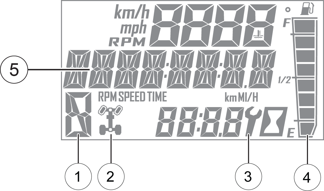
| Gear Indicator | This indicator displays gear shifter position H = High Gear L = Low Gear N = Neutral R = Reverse Gear P = Park -- = Gear Signal Error (or shifter between gears) |
|
| AWD Indicator | This indicator shows whether 2X4 or AWD is active when the vehicle is in gear. | |
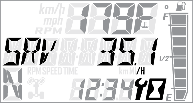
| Service Indicator | A flashing wrench symbol alerts the operator that the preset service interval has been reached. Your POLARIS dealer can provide scheduled maintenance. See Programmable Service Interval for resetting instructions. | |
| Fuel Gauge | The segments of the fuel gauge show the level of fuel in the fuel tank. When the last segment clears, a low fuel warning is activated. The outline of the fuel display will flash. Refuel immediately. | |
| Speed Limitation (if equipped) | This vehicle may be equipped with a maximum speed limitation function. This would be displayed on the screen as “LIM” followed by the speed. “LIM 30” for example. |
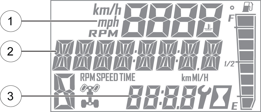
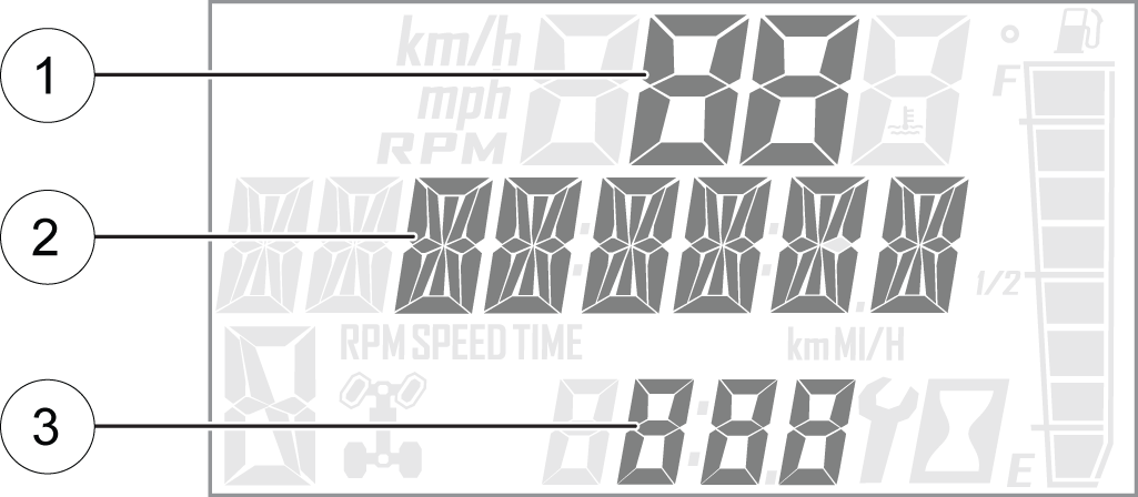
The rider information center contains three areas that display mode information.
| Description | |
| Engine Temperature | Temperature of engine coolant |
| Vehicle Speed | Speed of vehicle |
| Tachometer | Engine speed (RPM) |
| Description | |
| Odometer | The odometer records and displays the distance traveled by the vehicle. |
| Trip Meters (T1/T2) | A trip meter records the distance traveled by the vehicle if reset before each trip. To reset, see Trip Meter. |
| Engine Hours | Total hours of engine operation since manufacture |
| Service Hours | A flashing wrench symbol indicates that the preset service interval has been reached. To reset, see Programmable Service Interval. |
| Trip Time | Time length of vehicle operation since mode was last reset |
| Description | |
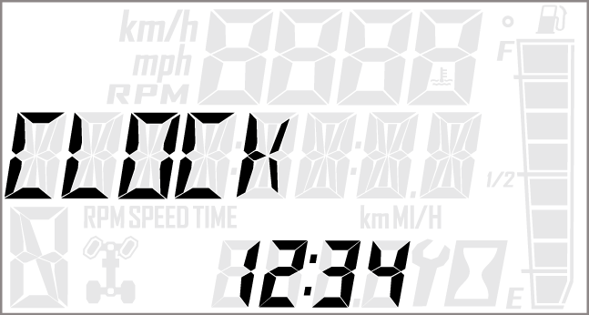
| Clock | The clock displays time in a 12-hour or 24-hour format. To reset, see Clock. |
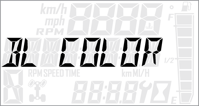
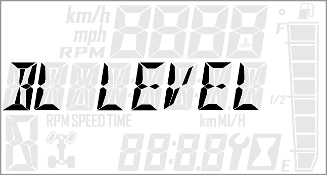
The information center backlight can be set to either blue or red.
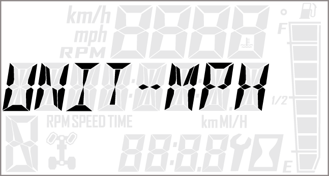
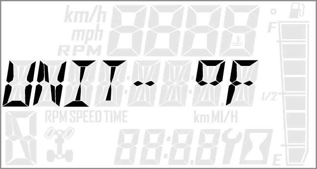
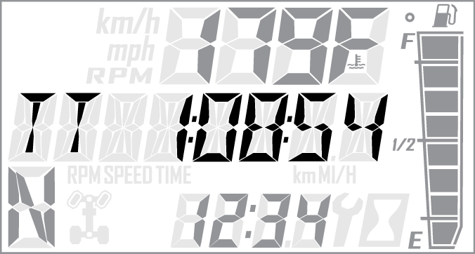
Use a trip meter to track the distance traveled during a specific trip or period of time. Reset the meter to zero before traveling.
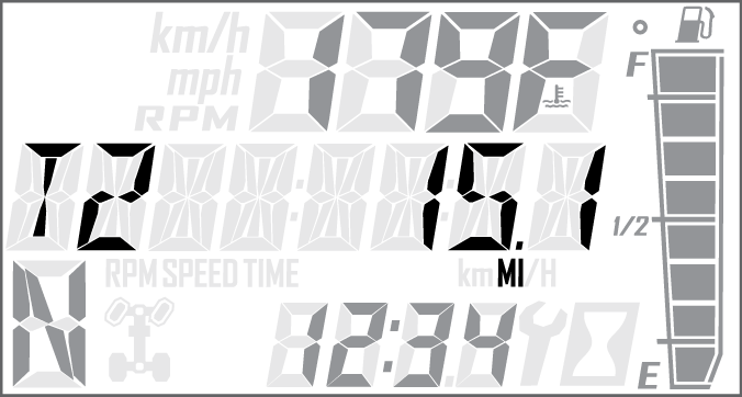
Use a trip time meter to track the travel time during a specific trip. Reset the meter to zero before traveling.
| NOTICE |
|
“OPTIONS” will display on the screen for 3 seconds before showing first menu item. |
| NOTICE |
| If PIN is lost or displaced please contact your Polaris dealer for assistance. |

Reference the image shown above:

Reference the image shown above:
| NOTE |
| The gauge will lock after 5 incorrect PIN entries. To unlock the gauge, power cycle the vehicle using the key ignition switch. |
| NOTICE |
| If the displayed code is an engine fault code, the CHECK ENGINE lamp will blink. If the displayed code is an EPS fault code, the EPS lamp will blink. |
| Diagnostic Codes | |||
|---|---|---|---|
| Component | Condition | SPN | FMI |
| Engine Control Module | |||
|
Accelerator Position 2 |
Data Erratic, Intermittent Or Incorrect |
29 |
2 |
|
Voltage Above Normal, Or Shorted To High Source |
29 |
3 |
|
|
Voltage Below Normal, Or Shorted To Low Source |
29 |
4 |
|
|
Throttle Position Sensor 1 |
Data Valid But Above Normal Operational Range - Most Severe Level |
51 |
0 |
|
Data Valid But Below Normal Operational Range - Most Severe Level |
51 |
1 |
|
|
Data Erratic, Intermittent Or Incorrect |
51 |
2 |
|
|
Voltage Above Normal, Or Shorted To High Source |
51 |
3 |
|
|
Voltage Below Normal, Or Shorted To Low Source |
51 |
4 |
|
|
Abnormal Rate Of Change |
51 |
10 |
|
|
Out Of Calibration |
51 |
13 |
|
|
Vehicle Speed Sensor |
Data Valid But Above Normal Operational Range - Most Severe Level |
84 |
0 |
|
Data Valid But Below Normal Operational Range - Most Severe Level |
84 |
1 |
|
|
Data Erratic, Intermittent Or Incorrect |
84 |
2 |
|
|
Voltage Above Normal, Or Shorted To High Source |
84 |
3 |
|
|
Voltage Below Normal, Or Shorted To Low Source |
84 |
4 |
|
|
Abnormal Frequency Or Pulse Width Or Period |
84 |
8 |
|
|
Abnormal Update Rate |
84 |
9 |
|
|
Abnormal Rate Of Change |
84 |
10 |
|
|
Bad Intelligent Device Or Component |
84 |
12 |
|
|
Received Network Data In Error |
84 |
19 |
|
|
Accelerator Position 1 |
Data Erratic, Intermittent Or Incorrect |
91 |
2 |
|
Voltage Above Normal, Or Shorted To High Source |
91 |
3 |
|
|
Voltage Below Normal, Or Shorted To Low Source |
91 |
4 |
|
|
Manifold Absolute Pressure Sensor |
Data Erratic, Intermittent Or Incorrect |
102 |
2 |
|
Voltage Above Normal, Or Shorted To High Source |
102 |
3 |
|
|
Voltage Below Normal, Or Shorted To Low Source |
102 |
4 |
|
|
Mechanical System Not Responding Or Out Of Adjustment |
102 |
7 |
|
|
Abnormal Rate Of Change |
102 |
10 |
|
|
Intake Air Temperature Sensor |
Data Erratic, Intermittent Or Incorrect |
105 |
2 |
|
Voltage Above Normal, Or Shorted To High Source |
105 |
3 |
|
|
Voltage Below Normal, Or Shorted To Low Source |
105 |
4 |
|
|
Abnormal Rate Of Change |
105 |
10 |
|
|
Data Valid But Above Normal Operating Range - Least Severe Level |
105 |
15 |
|
|
Engine Temperature Sensor |
Data Valid But Above Normal Operational Range - Most Severe Level |
110 |
0 |
|
Data Erratic, Intermittent Or Incorrect |
110 |
2 |
|
|
Voltage Above Normal, Or Shorted To High Source |
110 |
3 |
|
|
Voltage Below Normal, Or Shorted To Low Source |
110 |
4 |
|
|
Abnormal Rate Of Change |
110 |
10 |
|
|
Data Valid But Above Normal Operating Range - Least Severe Level |
110 |
15 |
|
|
Data Valid But Above Normal Operating Range - Moderately Severe Level |
110 |
16 |
|
|
Data Valid But Below Normal Operating Range - Least Severe Level |
110 |
17 |
|
|
System Power |
Data Valid But Above Normal Operational Range - Most Severe Level |
168 |
0 |
|
Data Valid But Below Normal Operational Range - Most Severe Level |
168 |
1 |
|
|
Voltage Above Normal, Or Shorted To High Source |
168 |
3 |
|
|
Voltage Below Normal, Or Shorted To Low Source |
168 |
4 |
|
|
Data Valid But Above Normal Operating Range - Moderately Severe Level |
168 |
16 |
|
|
Data Valid But Below Normal Operating Range - Moderately Severe Level |
168 |
18 |
|
|
Engine Speed |
Data Valid But Above Normal Operational Range - Most Severe Level |
190 |
0 |
|
Data Valid But Below Normal Operational Range - Most Severe Level |
190 |
1 |
|
|
Data Erratic, Intermittent Or Incorrect |
190 |
2 |
|
|
Mechanical System Not Responding Or Out Of Adjustment |
190 |
7 |
|
|
Received Network Data In Error |
190 |
19 |
|
|
Condition Exists |
190 |
31 |
|
|
Gear Sensor Signal |
Data Erratic, Intermittent Or Incorrect |
523 |
2 |
|
Voltage Above Normal, Or Shorted To High Source |
523 |
3 |
|
|
Voltage Below Normal, Or Shorted To Low Source |
523 |
4 |
|
|
Abnormal Update Rate |
523 |
9 |
|
|
ECU Memory |
Bad Intelligent Device Or Component |
628 |
12 |
|
Out Of Calibration |
628 |
13 |
|
|
Calibration |
Out Of Calibration |
630 |
13 |
|
Crankshaft Position Sensor |
Data Erratic, Intermittent Or Incorrect |
636 |
2 |
|
Abnormal Frequency Or Pulse Width Or Period |
636 |
8 |
|
|
Injector 1 (Front) (MAG) (SDI Port Injector) |
Voltage Above Normal, Or Shorted To High Source |
651 |
3 |
|
Voltage Below Normal, Or Shorted To Low Source |
651 |
4 |
|
|
Current Below Normal Or Open Circuit |
651 |
5 |
|
|
Fan Relay Driver Circuit |
Voltage Above Normal, Or Shorted To High Source |
1071 |
3 |
|
Voltage Below Normal, Or Shorted To Low Source |
1071 |
4 |
|
|
Current Below Normal Or Open Circuit |
1071 |
5 |
|
|
Ignition Coil Primary Driver 1 (Front) (MAG) |
Voltage Above Normal, Or Shorted To High Source |
1268 |
3 |
|
Voltage Below Normal, Or Shorted To Low Source |
1268 |
4 |
|
|
Current Below Normal Or Open Circuit |
1268 |
5 |
|
|
Fuel Pump Driver Circuit |
Voltage Above Normal, Or Shorted To High Source |
1347 |
3 |
|
Voltage Below Normal, Or Shorted To Low Source |
1347 |
4 |
|
|
Current Below Normal Or Open Circuit |
1347 |
5 |
|
|
Oxygen Sensor 1 |
Data Erratic, Intermittent Or Incorrect |
3056 |
2 |
|
Voltage Above Normal, Or Shorted To High Source |
3056 |
3 |
|
|
Voltage Below Normal, Or Shorted To Low Source |
3056 |
4 |
|
|
Bad Intelligent Device Or Component |
3056 |
12 |
|
|
ECU Output Supply Voltage 1 |
Data Valid But Above Normal Operational Range - Most Severe Level |
3597 |
0 |
|
Data Valid But Below Normal Operational Range - Most Severe Level |
3597 |
1 |
|
|
Voltage Above Normal, Or Shorted To High Source |
3597 |
3 |
|
|
Voltage Below Normal, Or Shorted To Low Source |
3597 |
4 |
|
|
Data Valid But Above Normal Operating Range - Moderately Severe Level |
3597 |
16 |
|
|
Data Valid But Below Normal Operating Range - Moderately Severe Level |
3597 |
18 |
|
|
ECU Output Supply Voltage 2 |
Data Valid But Above Normal Operational Range - Most Severe Level |
3598 |
0 |
|
Data Valid But Below Normal Operational Range - Most Severe Level |
3598 |
1 |
|
|
Voltage Above Normal, Or Shorted To High Source |
3598 |
3 |
|
|
Voltage Below Normal, Or Shorted To Low Source |
3598 |
4 |
|
|
Data Valid But Above Normal Operating Range - Moderately Severe Level |
3598 |
16 |
|
|
Data Valid But Below Normal Operating Range - Moderately Severe Level |
3598 |
18 |
|
|
ECU Output Supply Voltage 3 |
Data Valid But Above Normal Operational Range - Most Severe Level |
3599 |
0 |
|
Data Valid But Below Normal Operational Range - Most Severe Level |
3599 |
1 |
|
|
Voltage Above Normal, Or Shorted To High Source |
3599 |
3 |
|
|
Voltage Below Normal, Or Shorted To Low Source |
3599 |
4 |
|
|
Data Valid But Above Normal Operating Range - Moderately Severe Level |
3599 |
16 |
|
|
Data Valid But Below Normal Operating Range - Moderately Severe Level |
3599 |
18 |
|
|
ETC Accelerator Position Sensor Outputs 1 & 2 Correlation |
Data Erratic, Intermittent Or Incorrect |
65613 |
2 |
|
Throttle Position Sensor 2 |
Data Valid But Above Normal Operational Range - Most Severe Level |
520198 |
0 |
|
Data Valid But Below Normal Operational Range - Most Severe Level |
520198 |
1 |
|
|
Data Erratic, Intermittent Or Incorrect |
520198 |
2 |
|
|
Voltage Above Normal, Or Shorted To High Source |
520198 |
3 |
|
|
Voltage Below Normal, Or Shorted To Low Source |
520198 |
4 |
|
|
Abnormal Rate Of Change |
520198 |
10 |
|
|
Out Of Calibration |
520198 |
13 |
|
|
Fuel Correction Front |
Data Valid But Above Normal Operating Range - Least Severe Level |
520204 |
15 |
|
Data Valid But Below Normal Operating Range - Least Severe Level |
520204 |
17 |
|
|
All Wheel Drive Control Circuit |
Voltage Above Normal, Or Shorted To High Source |
520207 |
3 |
|
Voltage Below Normal, Or Shorted To Low Source |
520207 |
4 |
|
|
Current Below Normal Or Open Circuit |
520207 |
5 |
|
|
Oxygen Sensor Heater 1 |
Data Erratic, Intermittent Or Incorrect |
520209 |
2 |
|
Voltage Above Normal, Or Shorted To High Source |
520209 |
3 |
|
|
Voltage Below Normal, Or Shorted To Low Source |
520209 |
4 |
|
|
Current Below Normal Or Open Circuit |
520209 |
5 |
|
|
Accelerator Position/Brake Position Interaction |
Condition Exists |
520275 |
31 |
|
Throttle Position Sensor (1 or 2 Indeterminable) |
Data Erratic, Intermittent Or Incorrect |
520276 |
2 |
|
Bad Intelligent Device Or Component |
520276 |
12 |
|
|
Throttle Body Control - Power Stage |
Data Erratic, Intermittent Or Incorrect |
520277 |
2 |
|
Voltage Above Normal, Or Shorted To High Source |
520277 |
3 |
|
|
Voltage Below Normal, Or Shorted To Low Source |
520277 |
4 |
|
|
Abnormal Frequency Or Pulse Width Or Period |
520277 |
8 |
|
|
Condition Exists |
520277 |
31 |
|
|
Throttle Body Control - Return Spring Check Failed |
Condition Exists |
520278 |
31 |
|
Throttle Body Control - Adaption Aborted |
Condition Exists |
520279 |
31 |
|
Throttle Body Control - Limp Home Position Check Failed |
Condition Exists |
520280 |
31 |
|
Throttle Body Control - Mechanical Stop Adaptation Failure |
Condition Exists |
520281 |
31 |
|
Throttle Body Control - Repeated Adaptation Failed |
Condition Exists |
520282 |
31 |
|
Throttle Body Control |
Data Erratic, Intermittent Or Incorrect |
520283 |
2 |
|
Voltage Above Normal, Or Shorted To High Source |
520283 |
3 |
|
|
Voltage Below Normal, Or Shorted To Low Source |
520283 |
4 |
|
|
Throttle Body Control - Position Deviation Fault |
Condition Exists |
520284 |
31 |
|
ECU Monitoring Error |
Condition Exists |
520286 |
31 |
|
ECU Monitoring Error (Level 3) |
Condition Exists |
520287 |
31 |
|
ECU Monitoring of Injection Cut Off (Level 1) |
Condition Exists |
520288 |
31 |
|
ECU Monitoring of Injection Cut Off (Level 2) |
Condition Exists |
520289 |
31 |
|
Throttle Body Control - Requested Throttle Angle Not Plausible |
Condition Exists |
520305 |
31 |
|
ECU ADC Fault - No Load |
Condition Exists |
520306 |
31 |
|
ECU ADC Fault - Voltage |
Condition Exists |
520307 |
31 |
|
Accelerator Sensor Sync Fault - Sensor Diff Exceeds Limit |
Condition Exists |
520308 |
31 |
|
ECU Fault - ICO |
Condition Exists |
520309 |
31 |
|
ECU Fault - Hardware Disruption |
Condition Exists |
520311 |
31 |
|
Idle Fuel Correction Bank 1 |
Data Valid But Above Normal Operating Range - Least Severe |
520342 |
15 |
|
Data Valid But Below Normal Operating Range - Least Severe |
520342 |
17 |
|
|
Adaptive Fuel Correction Bank 1 |
Data Valid But Above Normal Operating Range - Least Severe |
520344 |
15 |
|
Data Valid But Below Normal Operating Range - Least Severe |
520344 |
17 |
|
|
EPAS Module |
|||
|
Steering Over Current Shut Down |
Current Above Normal Or Grounded Circuit |
520221 |
6 |
|
Steering Excessive Current Error |
Current Above Normal Or Grounded Circuit |
520222 |
6 |
|
Steering Torque Partial Failure |
Condition Exists |
520223 |
31 |
|
Steering Torque Full Failure |
Condition Exists |
520224 |
31 |
|
EPAS Inverter Temperature |
Data Valid But Above Normal Operational Range - Most Severe |
520225 |
0 |
|
Data Valid But Above Normal Operating Range - Severe |
16 |
||
|
EPAS Communications Receive Data Error |
Data Erratic, Intermittent Or Incorrect |
520226 |
2 |
|
Condition Exists |
520226 |
31 |
|
|
Position Encoder Error |
Root Cause Not Known |
520228 |
11 |
|
Bad Intelligent Device Or Component |
520228 |
12 |
|
|
Condition Exists |
520228 |
31 |
|
|
EPAS Software Error |
Bad Intelligent Device Or Component |
520229 |
12 |
|
Condition Exists |
520229 |
31 |
|
|
EPAS Power Save Condition |
Condition Exists |
520231 |
31 |
|
EPS SEPIC Voltage Error |
Voltage Above Normal, Or Shorted To High Source |
524086 |
3 |
|
Voltage Below Normal, Or Shorted To Low Source |
524086 |
4 |
|
|
Calibration CRC |
Checksum/CRC Error |
630 |
13 |
|
Steering Torque Full Failure |
Torque Sensor Out of Range |
520223 |
31 |
|
Torque Sensor Linearity Error |
520224 |
31 |
|
|
EPS CAN Communications Receive Error |
No RX Message for {{cal parameter}} seconds |
520226 |
2 |
|
Vehicle Speed |
Vehicle Speed Too High |
84 |
0 |
|
Vehicle Speed Implausible |
10 |
||
|
Received Vehicle Speed has Errors |
19 |
||
|
Engine Speed |
Engine Speed Too High |
190 |
0 |
|
Received Engine Speed has Errors |
190 |
19 |
|
|
Battery Voltage |
Too High |
168 |
3 |
|
Battery Voltage |
Too Low |
168 |
4 |
|
Position Encoder Error |
Loss of SPI Communication |
520228 |
12 |
|
Encoder Variance Error |
31 |
||
|
EPS Software Error |
Manufacturing CRC Error |
520229 |
12 |
|
Boot Count Error |
31 |
||
|
ICS Communication |
Loss of CAN between EPS and Instrument Cluster |
520230 |
31 |
|
EPAS Power Save |
5 minute time out |
520231 |
31 |
|
ECU Memory |
EEPROM Communication Error |
628 |
12 |
|
Application CRC Error |
13 |
||
|
VGD Low |
VGD Low |
524086 |
4 |
|
Absolute Position Sensor |
Absolute Position Sensor Out of Range |
1807 |
31 |
|
Absolute Position Sensor Not Calibrated |
1807 |
13 |
|
© Copyright Polaris Inc. All rights reserved.