
Content Source: Polaris Power® P5500 and P6500 Owner’s Manual (9931064 R02) > Features and Controls Chapter
| IMPORTANT |
|
The Owner's Manual for this vehicle contains warnings, instructions and other information you must read and fully understand before safely riding or performing maintenance on this vehicle.Always follow the warnings and instructions in Owner's Manual. Click the CONTENTS link above for the Table Of Contents, or download a full PDF of the Owner Manual in the Owner Support area of Polaris.com |
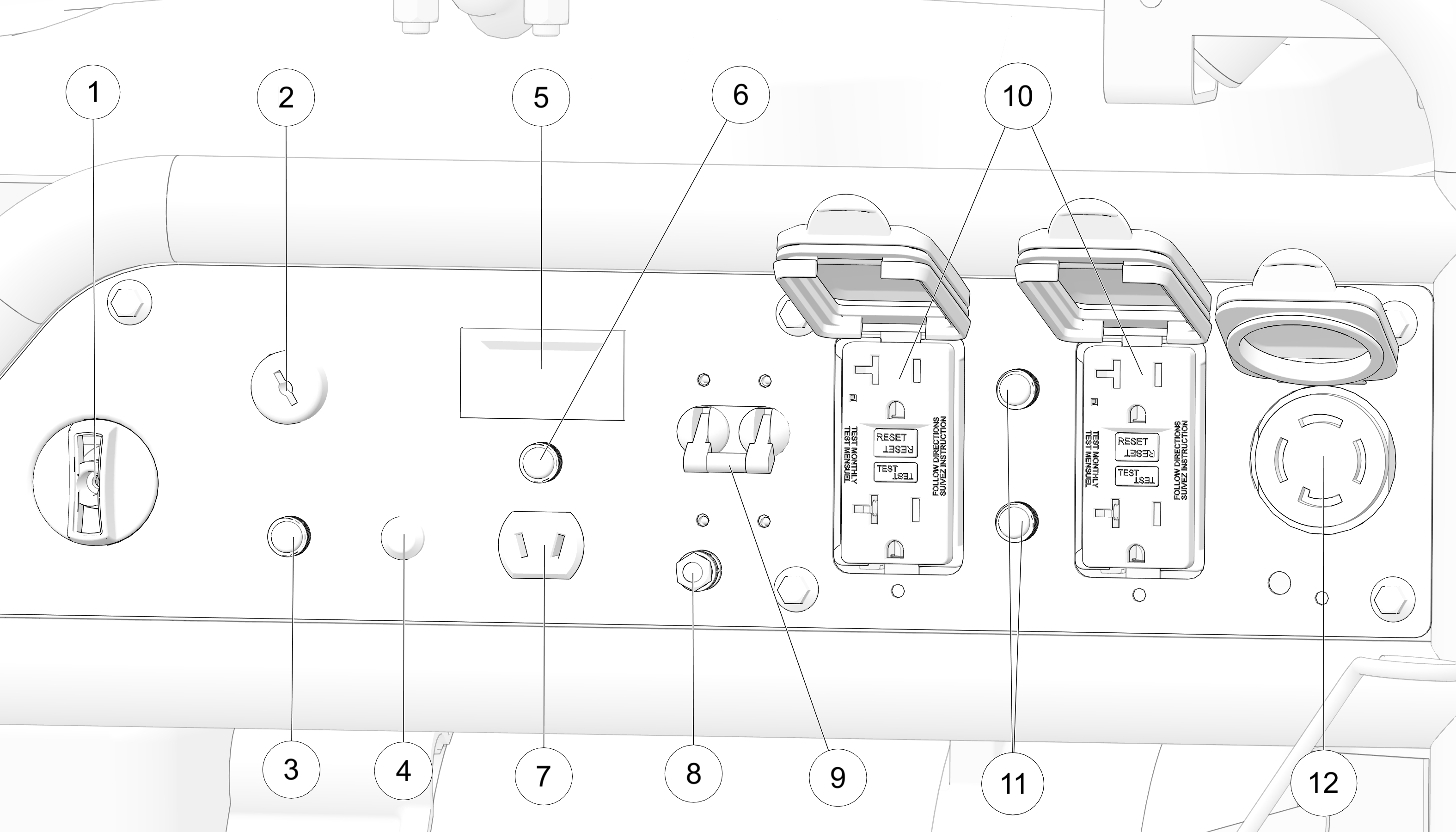
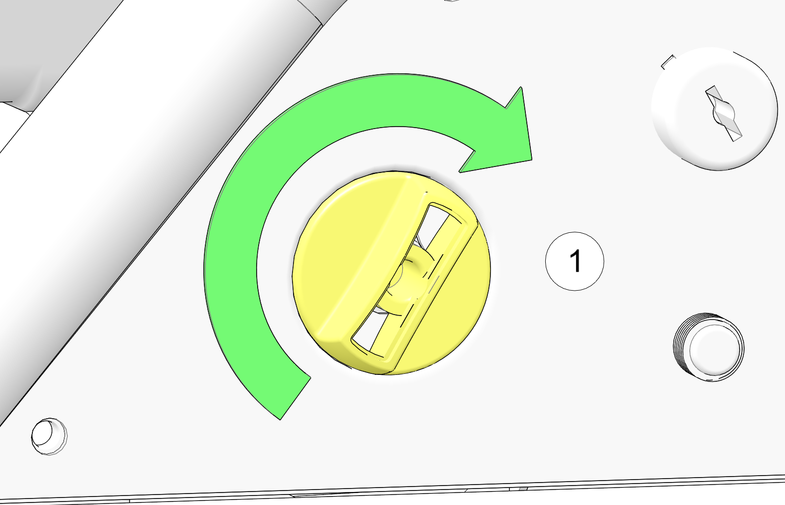
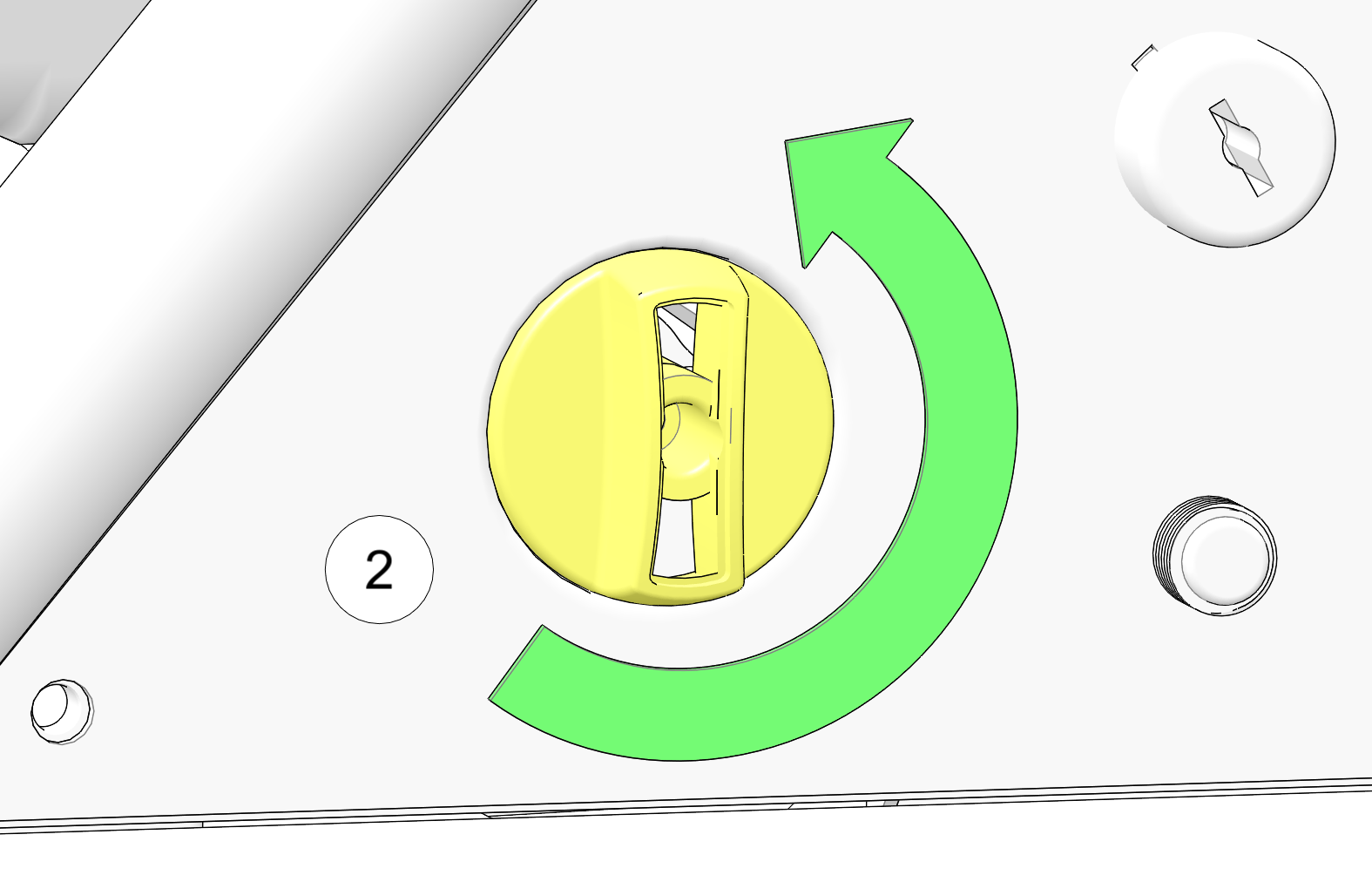
The ignition switch ![]() must be in the ON / RUN position for the generator to operate.
must be in the ON / RUN position for the generator to operate.
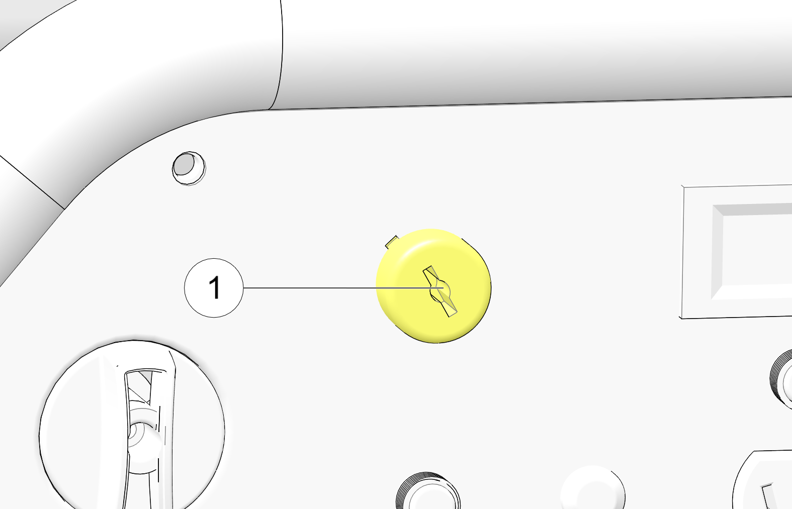
The indicator light will illuminate GREEN when the engine is running.
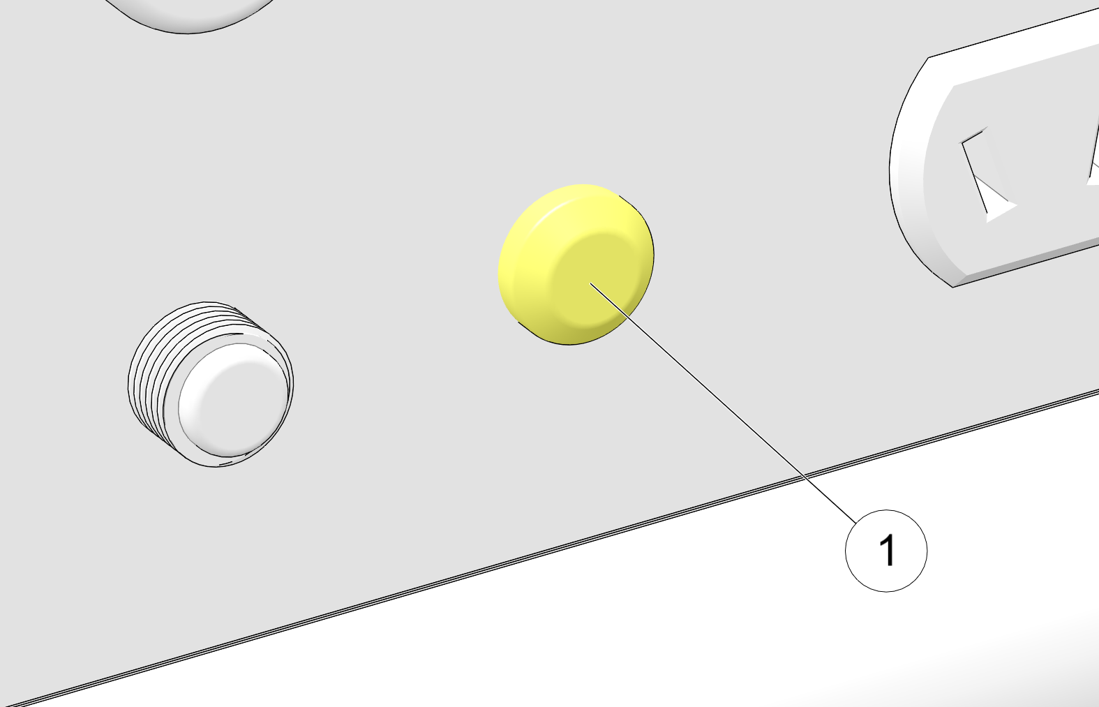
| IMPORTANT |
| The overload reset button is available for a maximum of 5 times for each full start of the generator. Shut down the generator and restart using power switch in order to refresh number of resets. |
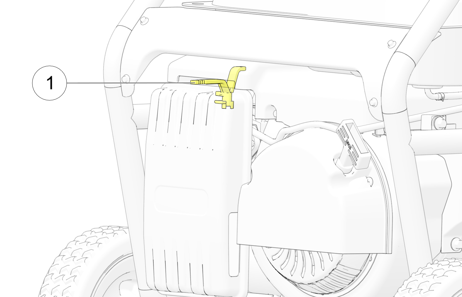
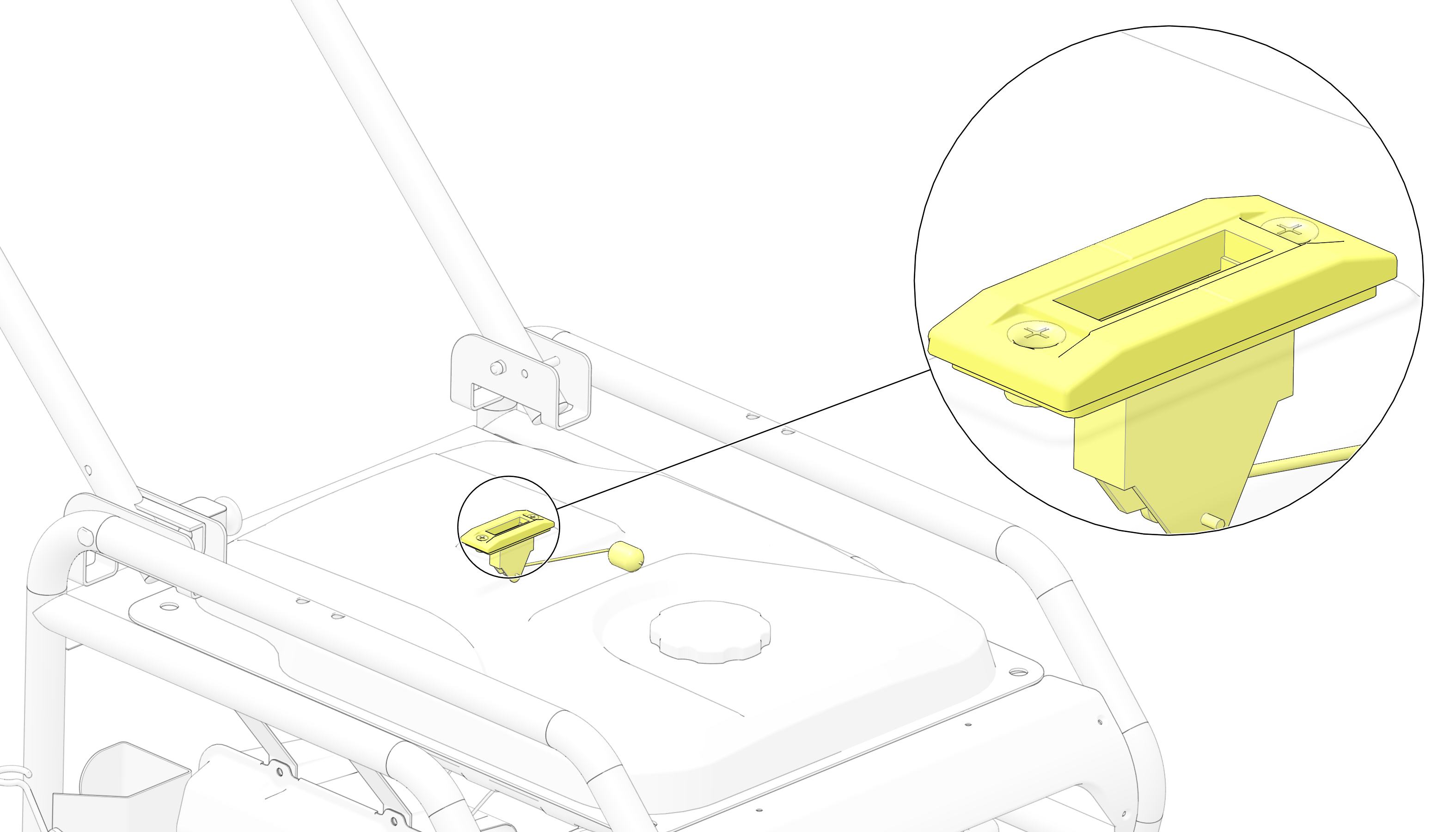
The Fuel Volume Indicator provides an indication of fuel quantity.
| NOTICE |
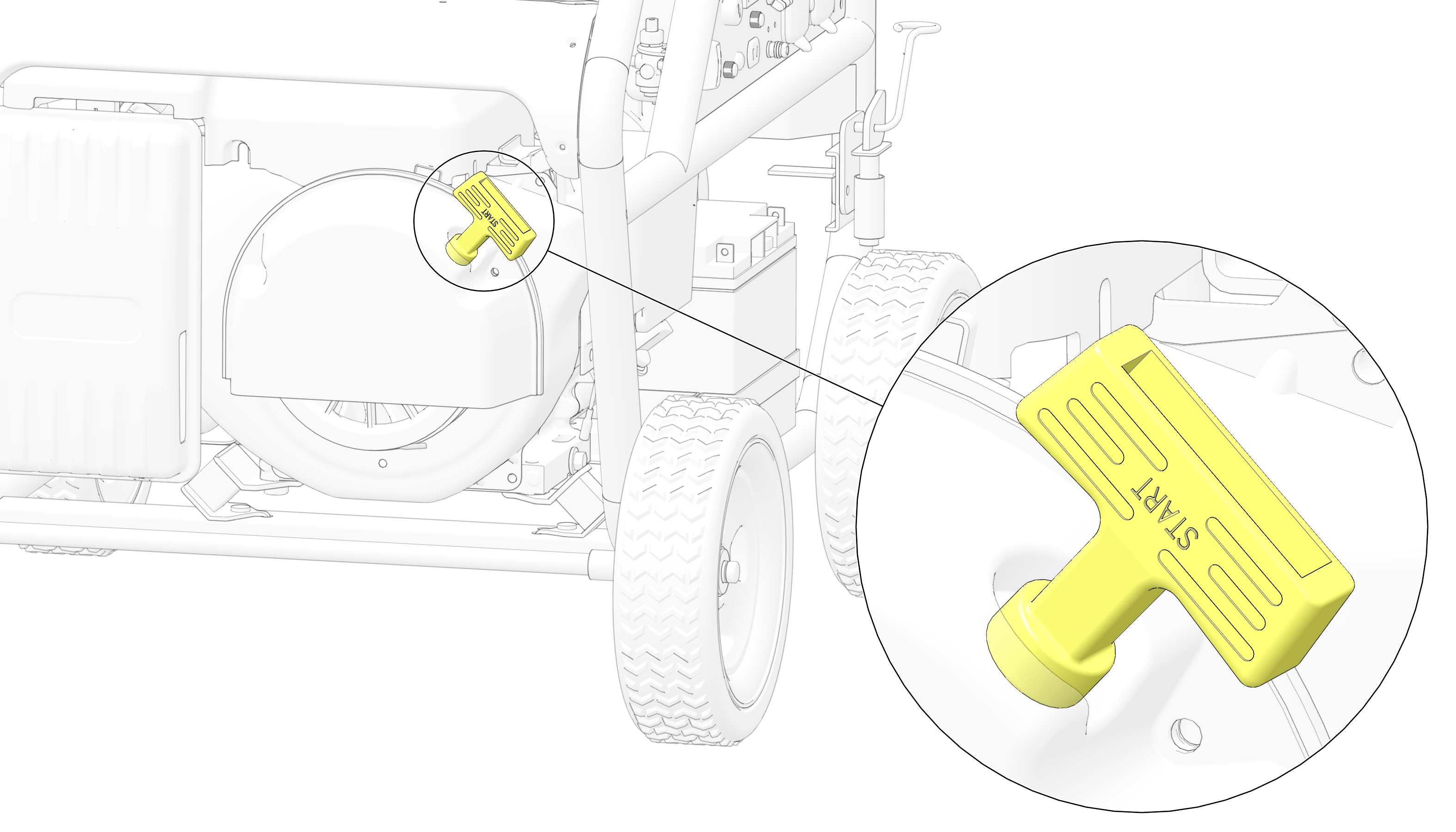
| Do not allow starter grip to snap back against the generator. Return it gently to prevent damage to the starter. The starter recoil grip causes the recoil starter to crank the engine when pulled. |
| NOTICE |
| Consult a qualified electrician, electrical inspector, or local agency having jurisdiction for local codes or ordinances for the intended use of the generator before using the ground terminal. |
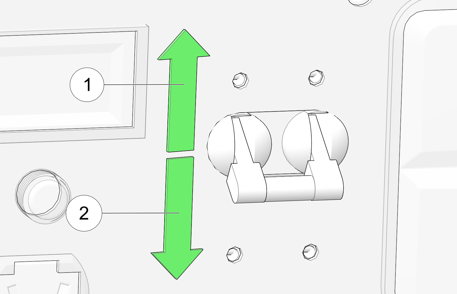
The circuit breaker will automatically switch off if a short circuit or significant overload of the generator occurs to the
240V receptacle.
If the circuit breaker switches OFF ![]() automatically, check that all connected appliances are working properly and do not exceed the generator’s maximum output
before switching the breaker back to the ON
automatically, check that all connected appliances are working properly and do not exceed the generator’s maximum output
before switching the breaker back to the ON ![]() position.
position.
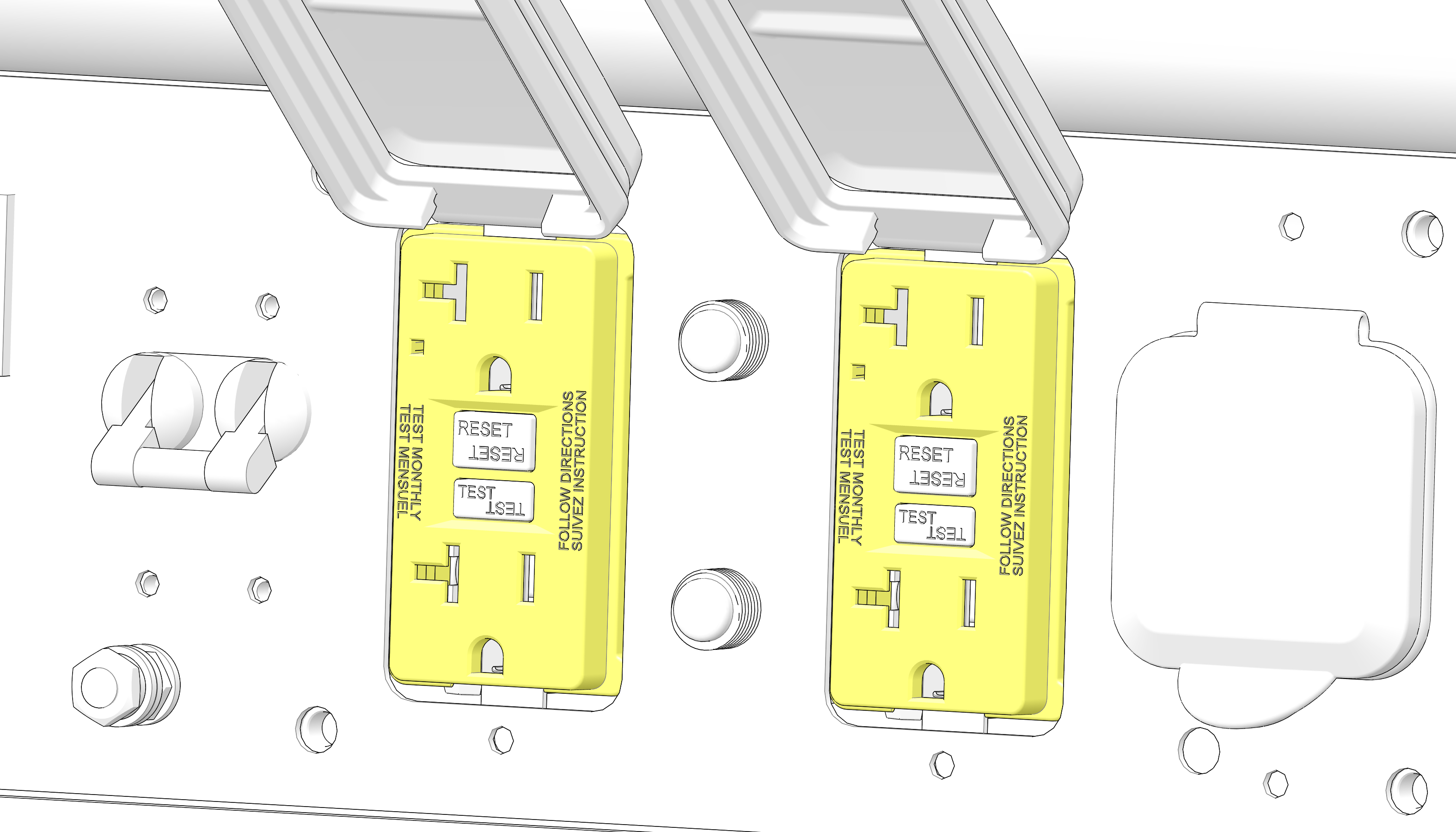
The AC receptacles provide four connections for properly rated AC appliances.
The twist-lock AC receptacle ![]() provides connection for properly rated, 120V and 240V AC appliances.
provides connection for properly rated, 120V and 240V AC appliances.
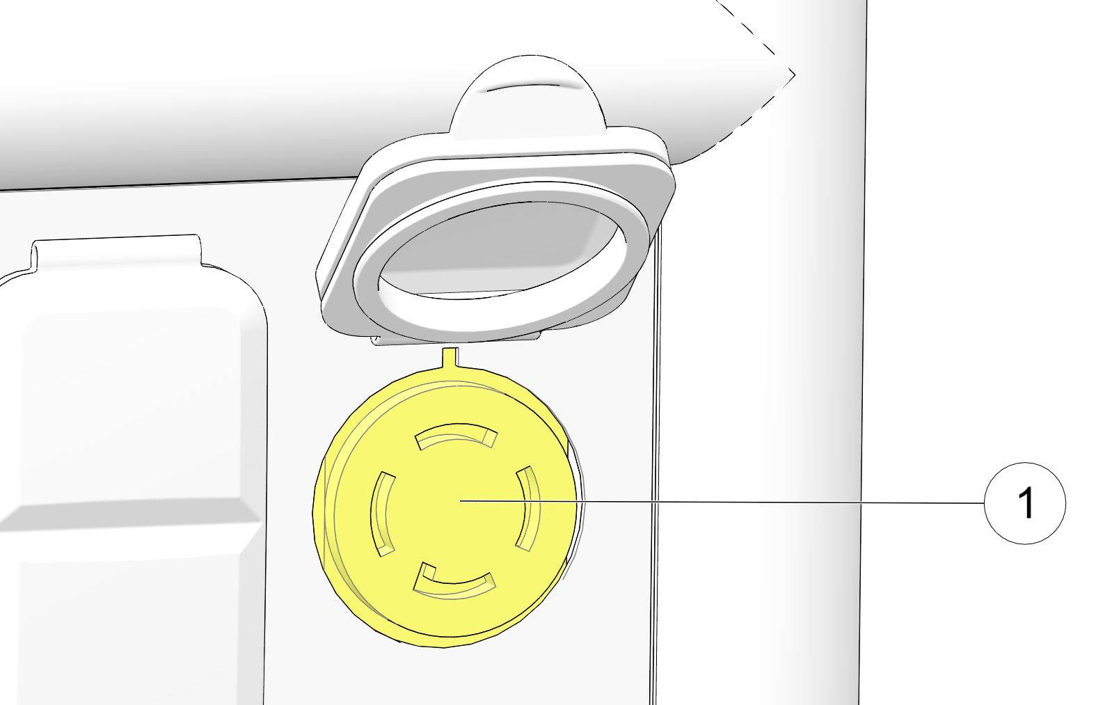
| P5500i | P6500i | ||
|---|---|---|---|
| Voltage | Ampage | Voltage | Ampage |
| 120 V | 46 amps | 120 V | 54 amps |
| 240 V | 23 amps | 240 V | 27 amps |
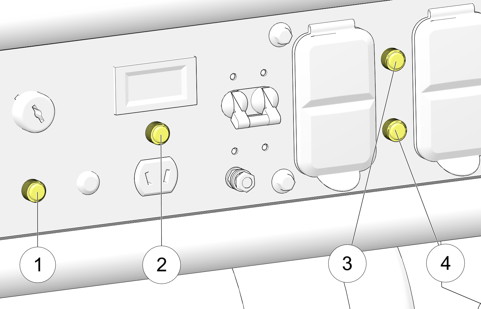
This receptacle is protected from an overload with a circuit protector. If the DC circuit is overloaded, the protector will
open and power to the DC receptacle will cease.
The protector is located above the receptacle and is closed by pressing down on the button.
© Copyright Polaris Inc. All rights reserved.