
Content Source: Polaris Power® P3200iE Owner’s Manual (9931063 R03) > Features and Controls Chapter
| IMPORTANT |
|
The Owner's Manual for this vehicle contains warnings, instructions and other information you must read and fully understand before safely riding or performing maintenance on this vehicle.Always follow the warnings and instructions in Owner's Manual. Click the CONTENTS link above for the Table Of Contents, or download a full PDF of the Owner Manual in the Owner Support area of Polaris.com |
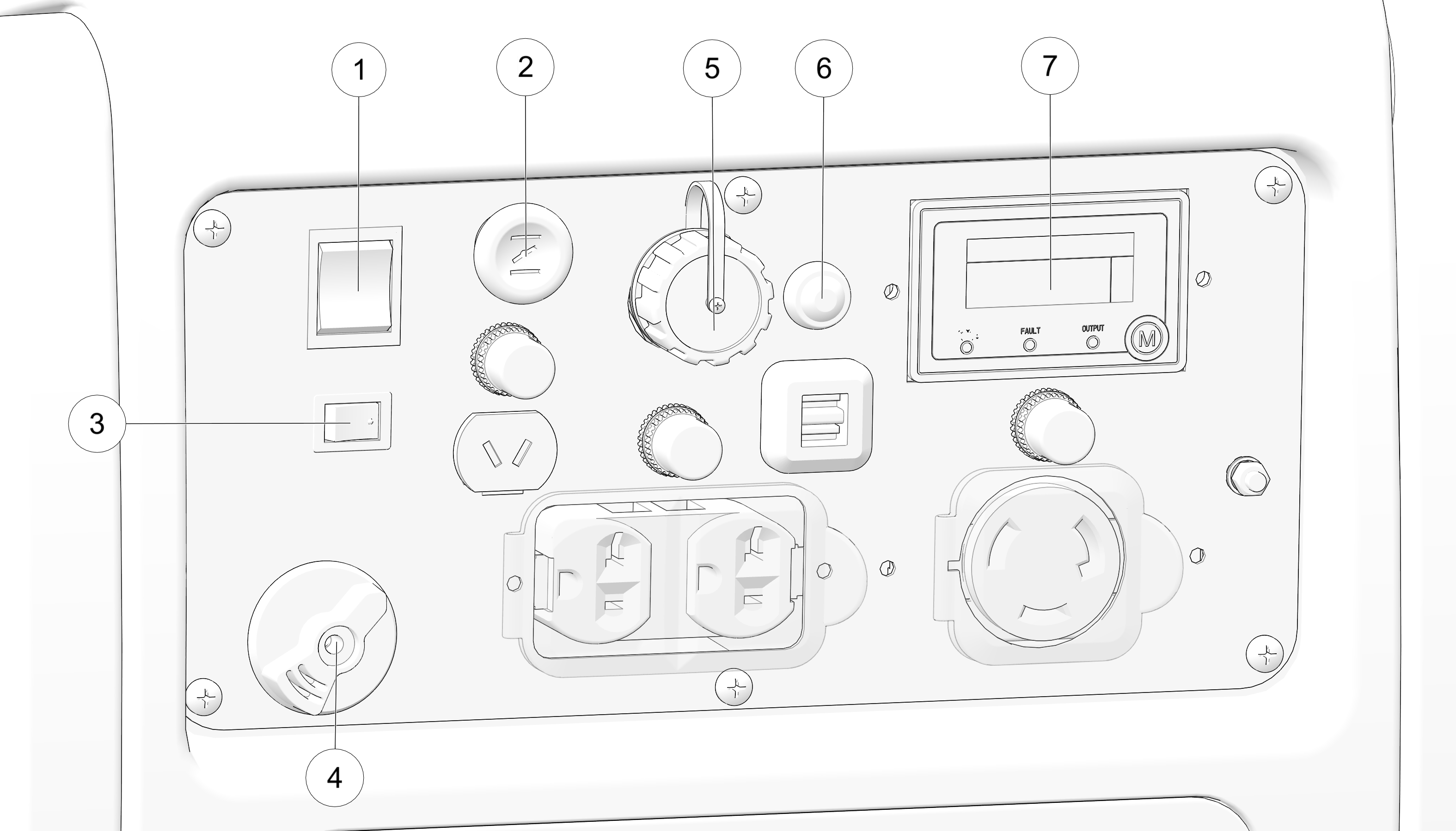
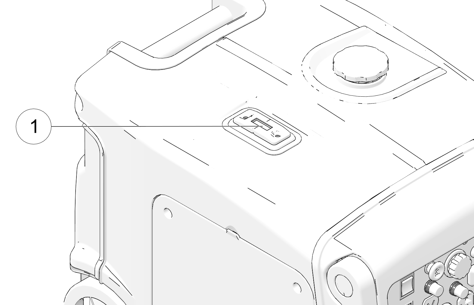
Press SMART throttle switch to ON position to automatically reduces engine speed when loads are shut off or disconnected. The engine will return to the proper speed when appliances are in use or reconnected.

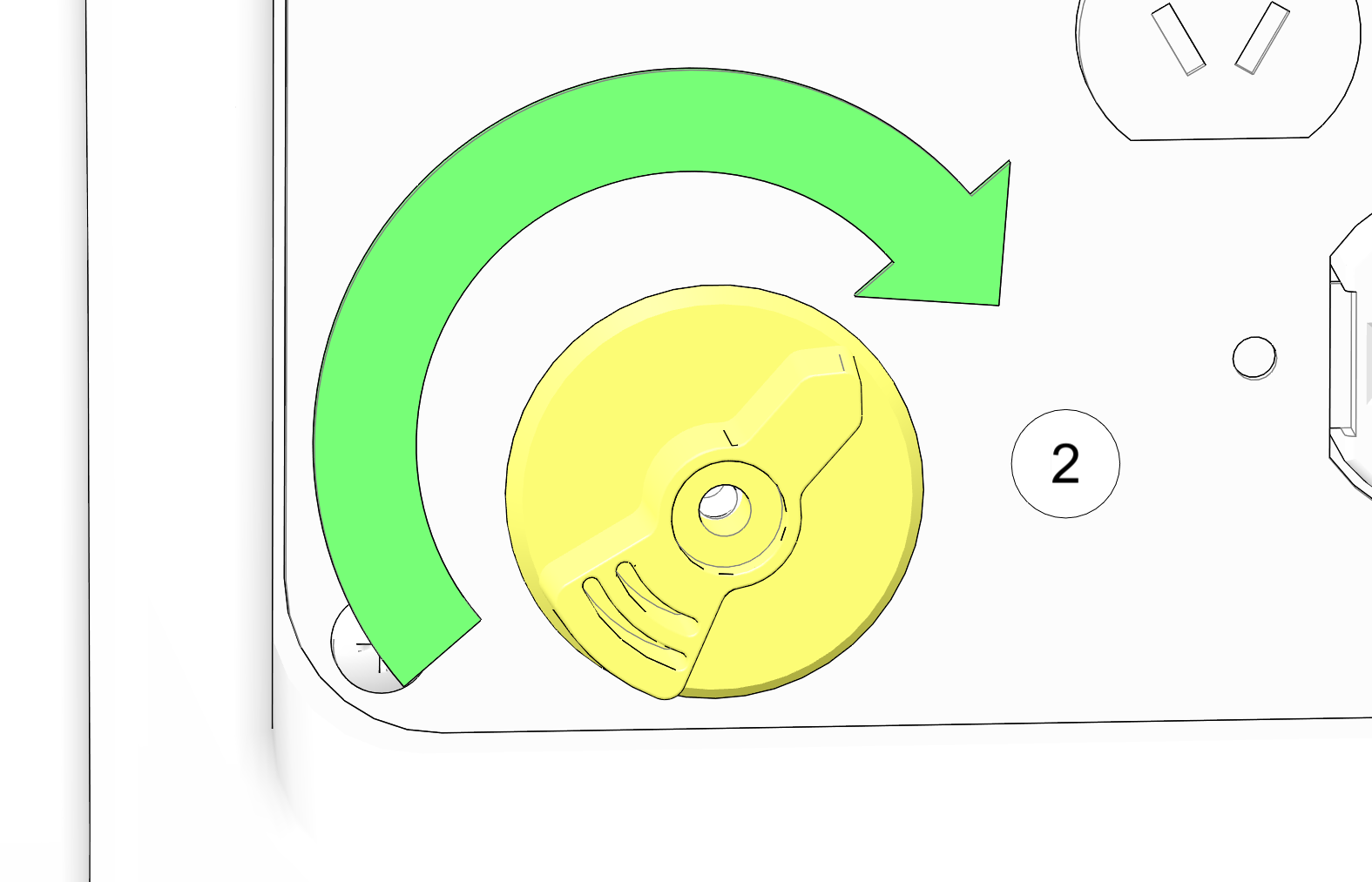
In the case of engine overload:
| IMPORTANT |
| The overload reset button is available for a maximum of 5 times for each full start of the generator. Shut down the generator and restart using power switch in order to refresh number of resets. |
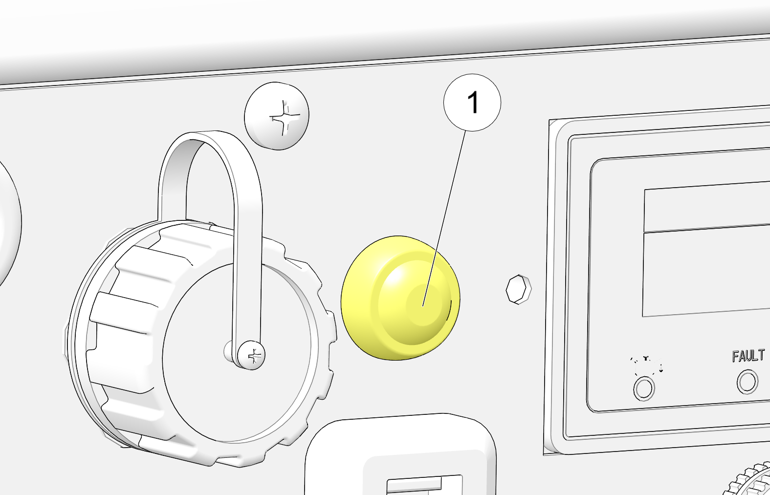
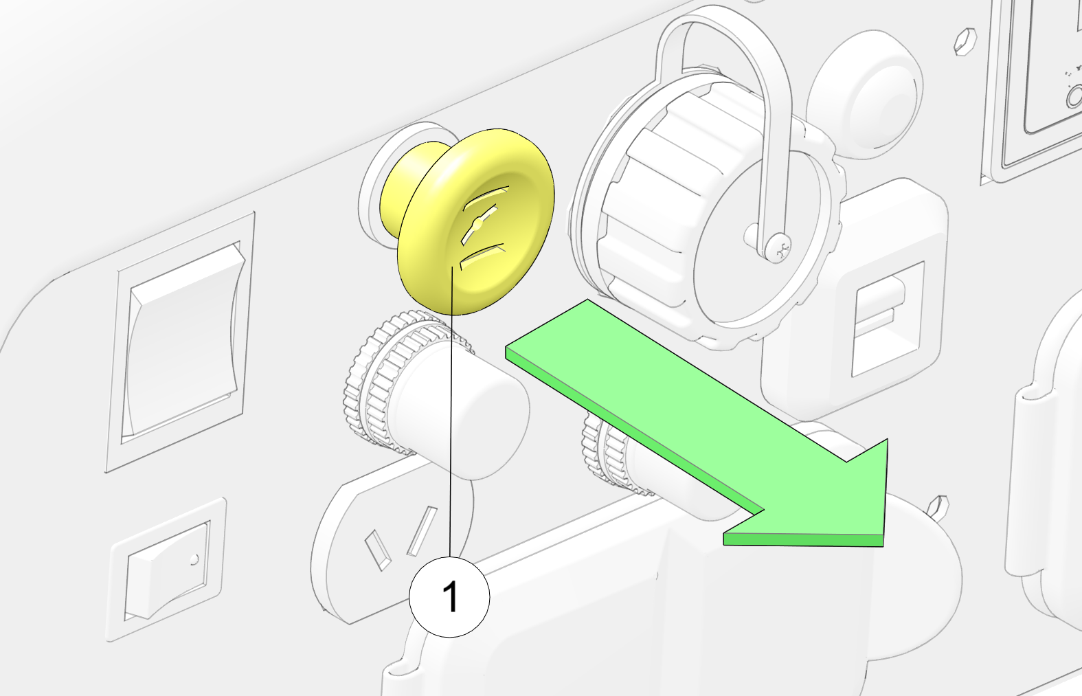
Pulling the choke lever ![]() provides proper fuel-starting mixture when the engine is cold. When attempting to start a cold engine, pull the choke lever
outward to close. Slowly return the choke to the open position as the engine warms.
provides proper fuel-starting mixture when the engine is cold. When attempting to start a cold engine, pull the choke lever
outward to close. Slowly return the choke to the open position as the engine warms.
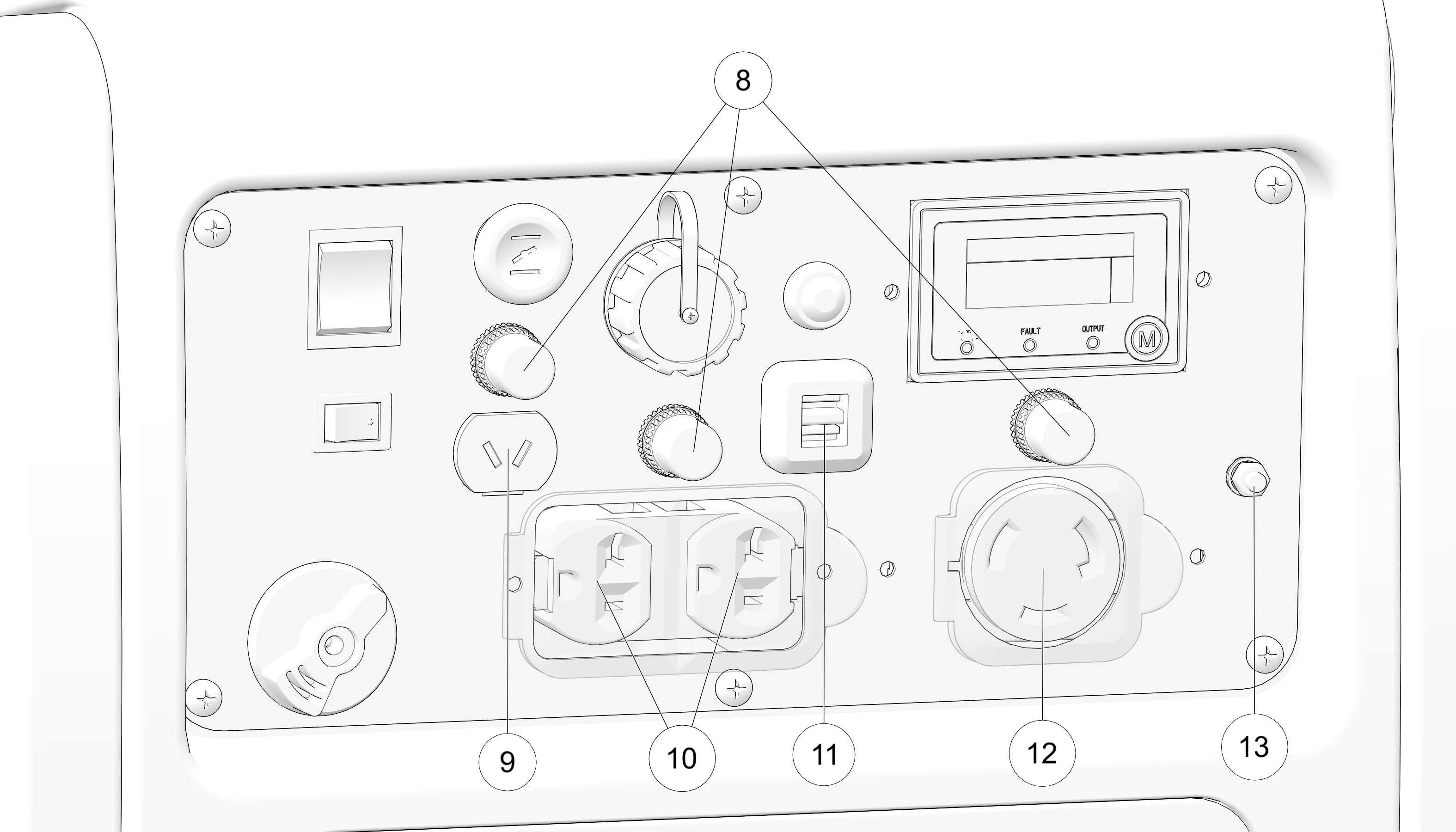
The Fuel Volume Indicator ![]() provides an indication of fuel quantity.
provides an indication of fuel quantity.
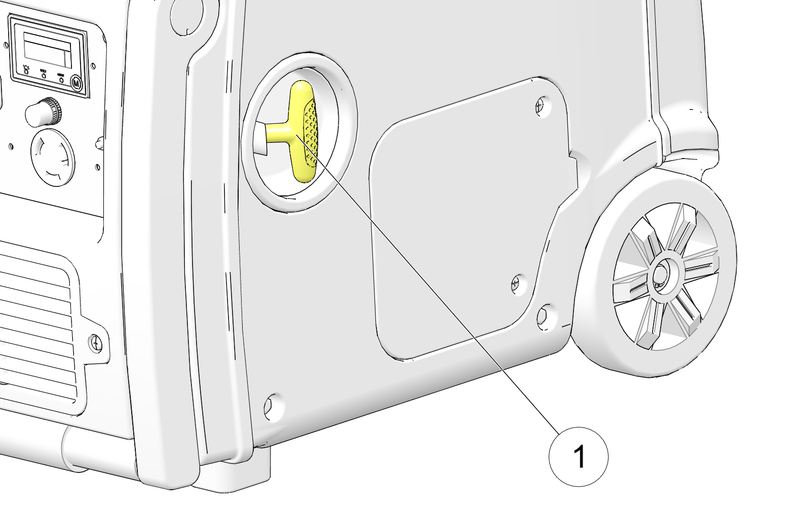
| NOTE |
| Do not allow starter grip to snap back against the generator. Return it gently to prevent damage to the starter. The starter
recoil grip |
The recoil starter ![]() is used as a secondary engine starter if the battery does not contain adequate charge to operate the starter motor.
is used as a secondary engine starter if the battery does not contain adequate charge to operate the starter motor.
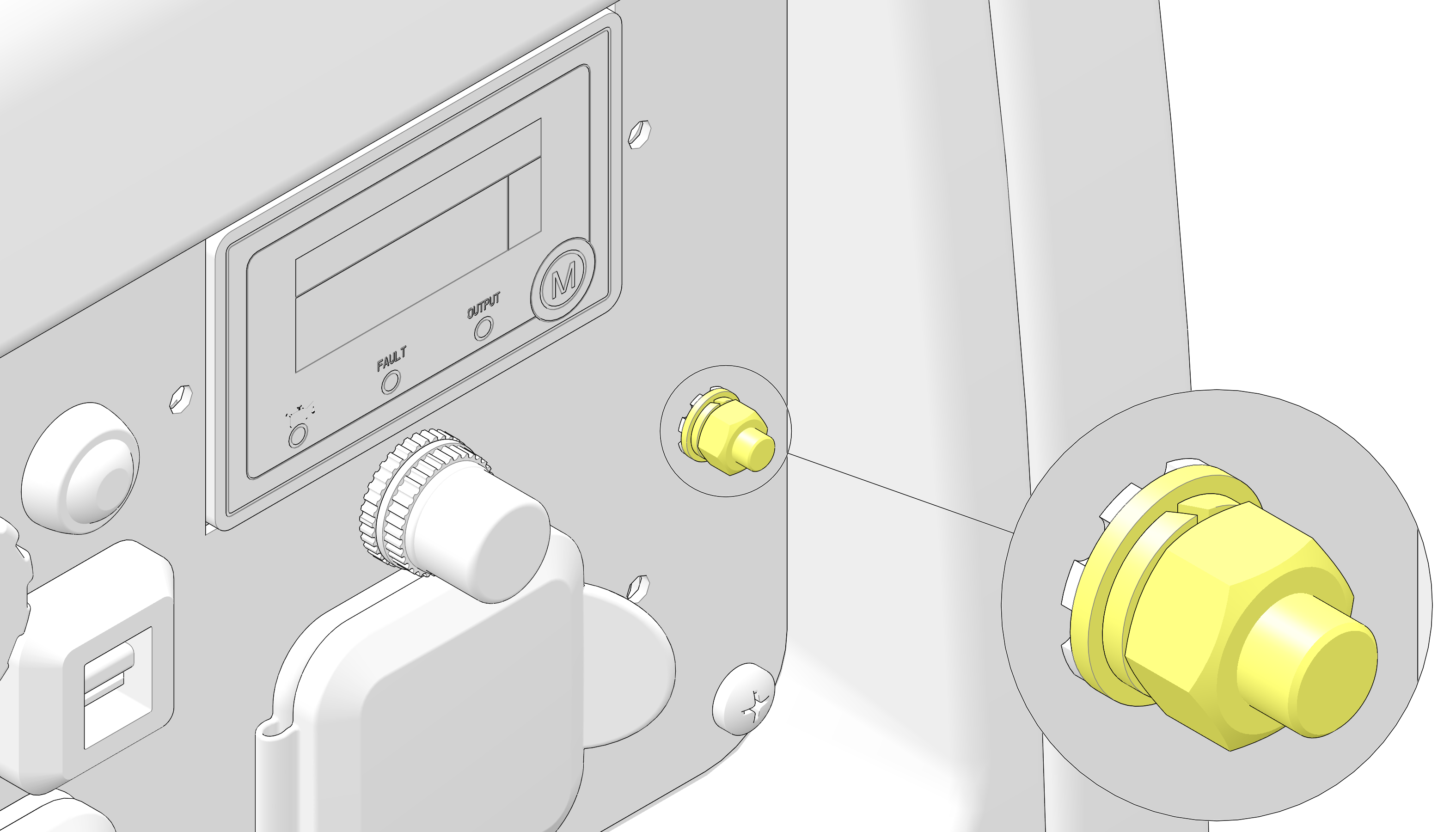
| NOTE |
| Consult a qualified electrician, electrical inspector, or local agency having jurisdiction for local codes or ordinances for the intended use of the generator before using the ground terminal. |
The ground terminal connects to the frame of the generator, metal parts that do not conduct current, and ground terminals of each receptacle.
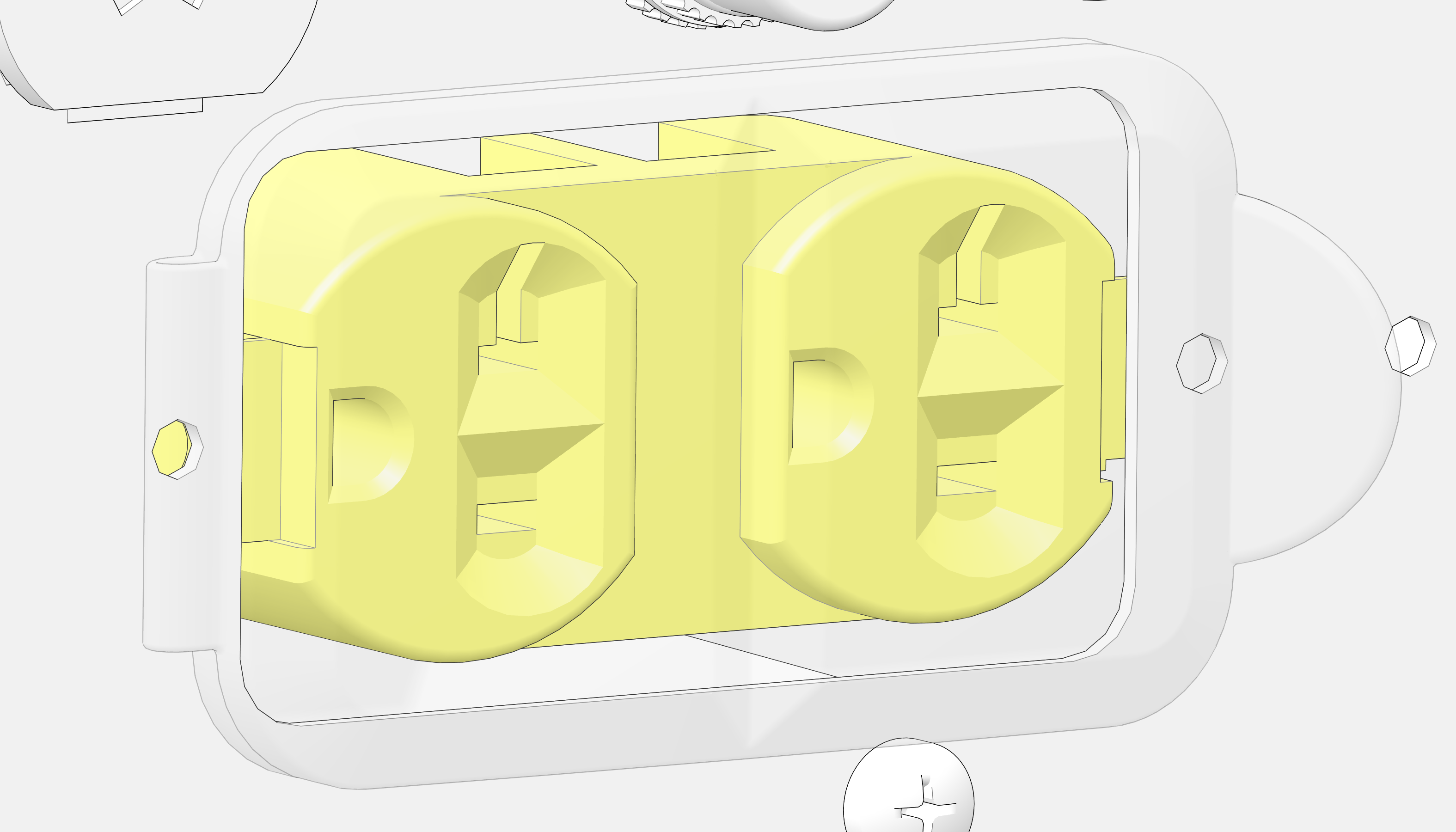
The AC receptacles provide two connections for properly rated AC appliances.
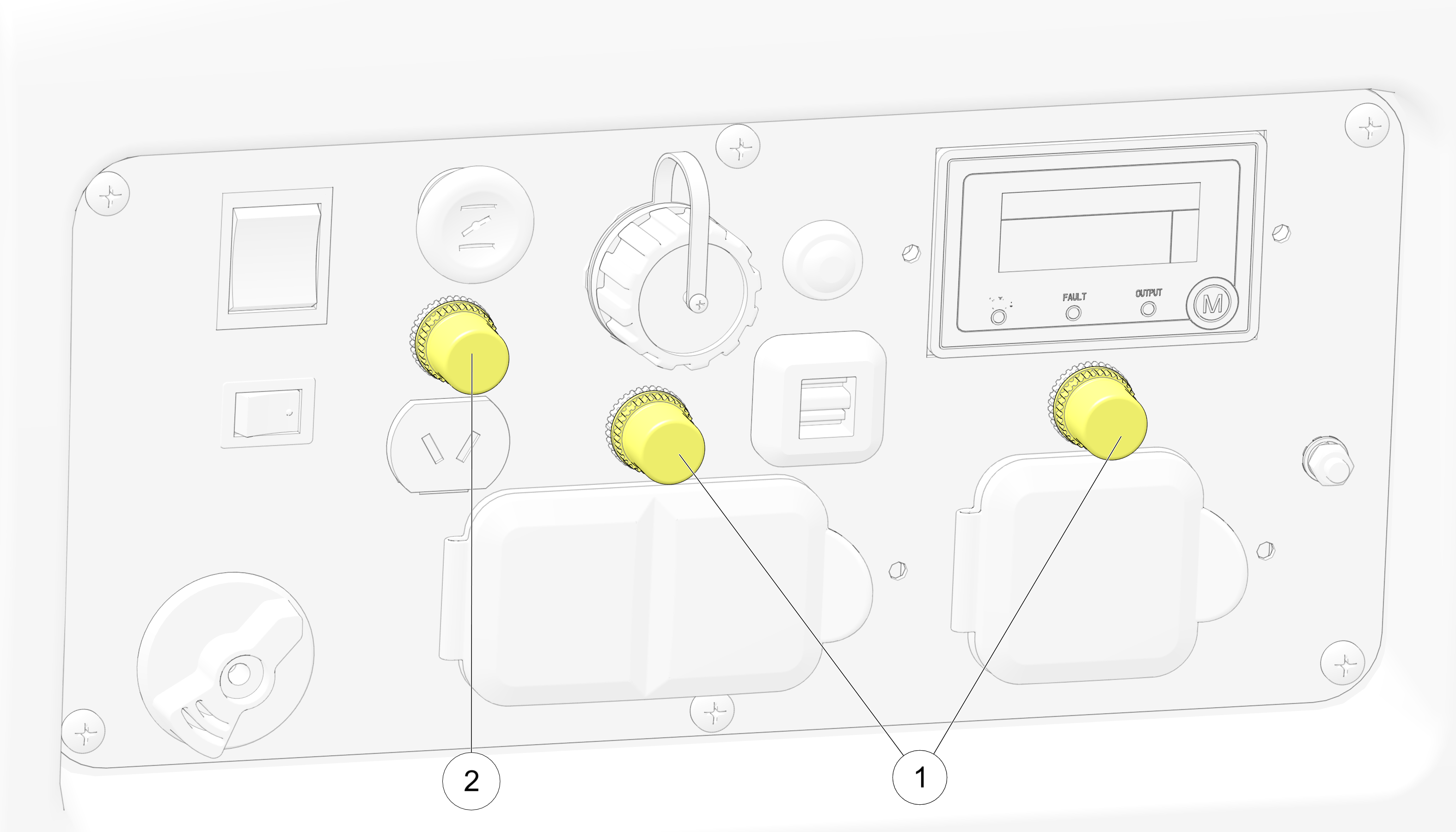
| NOTICE |
| Prior to resetting the circuit breaker, check appliances for proper operation and that rated load capacity has not been exceeded. |
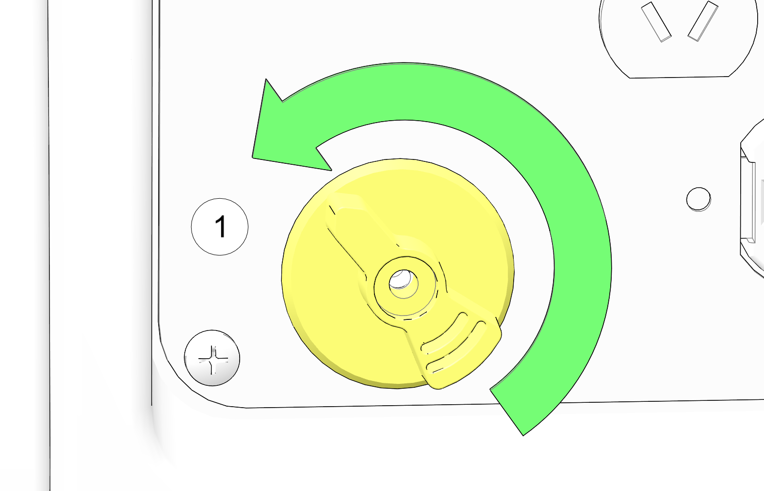
This receptacle is protected from an overload with a circuit protector. If the DC circuit is overloaded, the protector will
open and power to the DC receptacle will cease.
The protector is located above the receptacle and is closed by pressing down on the button.

120V AC receptacle ![]() provides connection for properly rated, 120V AC appliances.
provides connection for properly rated, 120V AC appliances.
120V / 30 Amp

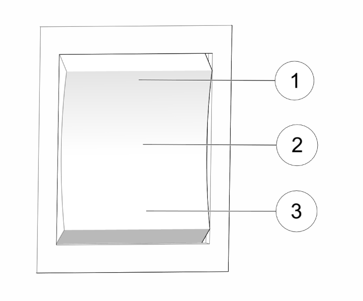
| Indicator Light | Description | |
|---|---|---|
 |
Low Oil Indicator | The low oil alarm system is designed to prevent engine damage caused by an insufficient amount of oil in the crankcase. Before
the oil level in the crankcase falls below a safe limit, the low oil alarm system will automatically shut down the engine
(the engine switch will remain in the ON position). If the low oil alarm system shuts down the engine the red low oil alarm indicator light will come on when you operate the starter, and the engine will not run. If this occurs, search for any oil leaks. Add engine oil to resume normal operation. See Oil Recommendation for oil recommendation. |
 |
Fault / Overload Indicator | If a short circuit occurs in a connected appliance(s), or if the generator is overloaded (produces more than 2800 W), current to the connected appliance will cease, the output indicator (GREEN) will extinguish, and the overload indicator will illuminate RED. |
 |
Output Indicator | The output indicator illuminates GREEN when the generator is in normal operation and producing electrical power at the receptacles. |
The system seamlessly matches frequency and automatically distributes the load to each generator evenly so neither is overloaded.
Contact your dealer to purchase a POLARIS parallel kit.

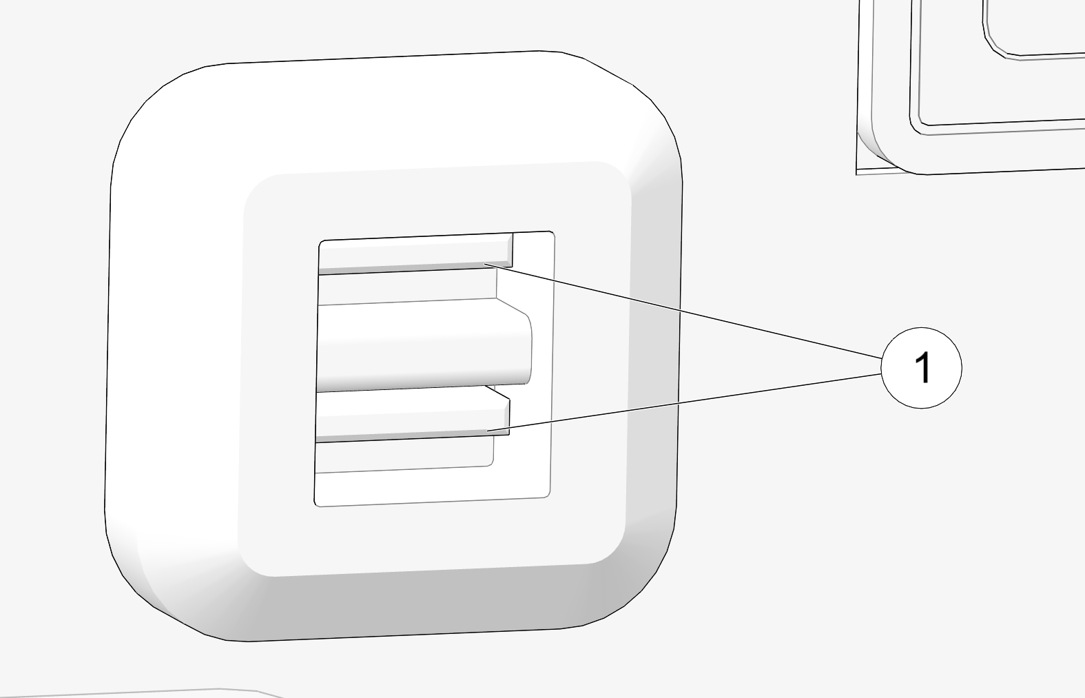
This generator is equipped with two USB ports ![]() . A total of 3.1A data transfer speed is available at 5 volts.
. A total of 3.1A data transfer speed is available at 5 volts.
Each single port can draw the full 3.1A or will be distributed as needed.
© Copyright Polaris Inc. All rights reserved.