Content Source: 2020 RANGER XP 1000 Tractor Owner’s Manual (9930868 R02) > Maintenance Chapter

IMPORTANT

The Owner's Manual for this vehicle contains warnings, instructions and other information you must read and fully understand before safely riding or performing maintenance on this vehicle.Always follow the warnings and instructions in Owner's Manual.

Click the CONTENTS link above for the Table Of Contents, or download a full PDF of the Owner Manual in the Owner Support area of Polaris.com

POLARIS Variable Transmission (PVT) System

WARNING
Failure to comply with the instructions in this warning can result in severe injury or death. Do not modify any component of the PVT system. Doing so may reduce its strength so that a failure may occur at a high speed. The PVT system has been precision balanced. Any modification will cause the system to be out of balance, creating vibration and additional loads on components.
The PVT system rotates at high speeds, creating large amounts of force on clutch components. As the owner, you have the following responsibilities for your own safety and the safety of others:
  • Always follow all recommended maintenance procedures. Always look for and remove debris inside and around the clutch and vent system when replacing the belt.
  • See your dealer or other qualified service person as outlined in the owner's manual.
  • This PVT system is intended for use on POLARIS products only. Do not install it in any other product.
  • Always make sure the PVT housing is securely in place during operation.

Belt Removal

If a belt fails, always clean any debris from the clutch air duct and from the clutch and engine compartments when replacing the belt.
WARNING
Failure to remove ALL debris when replacing the belt could result in vehicle damage, loss of control and severe injury or death.
NOTE
Inspect the entire clutch outlet duct (including the outlet duct screen) when replacing a drive belt. Remove any debris found in the outlet duct or outlet duct screen.
To remove the belt, do the following:
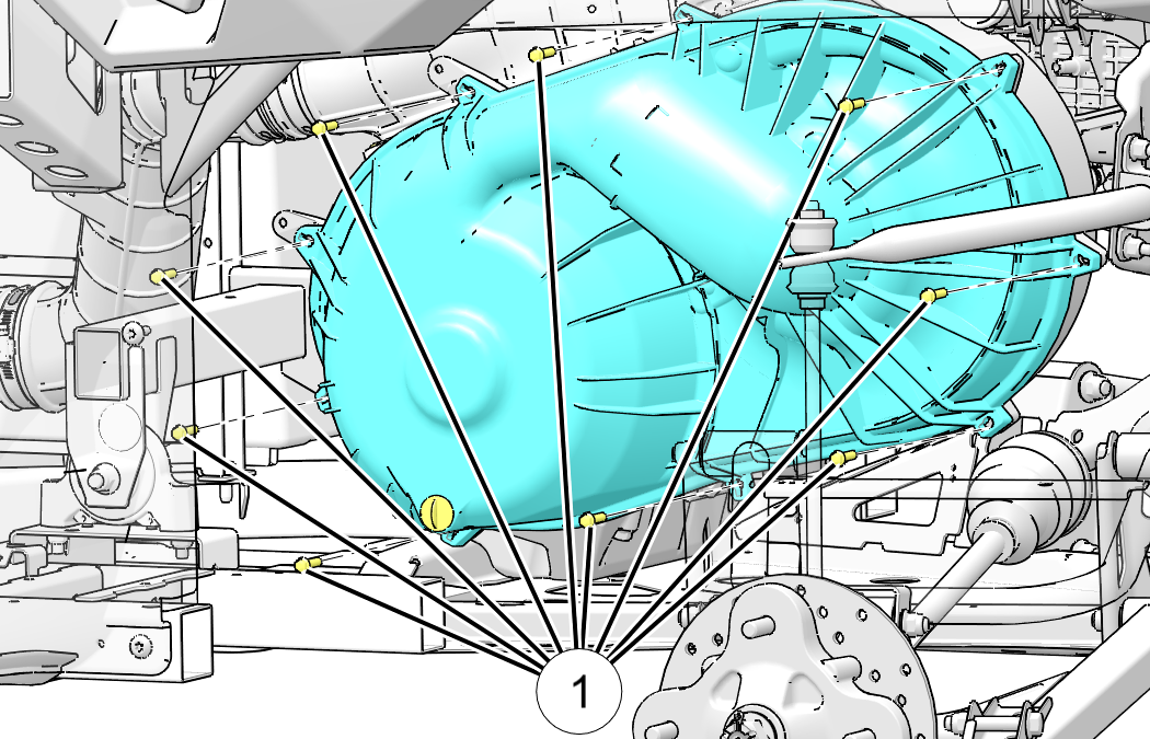
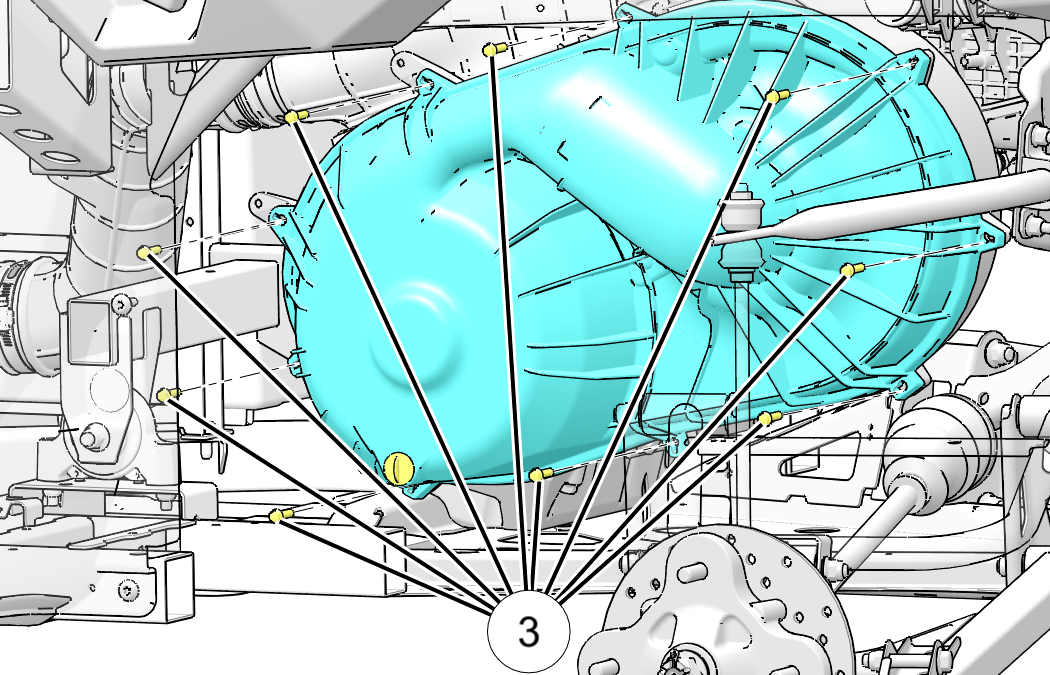
  1. Remove the nine fasteners that retain the outer clutch cover.

    Image

    Image
    NOTE

    Removal of left rear wheel or left rear shock is NOT necessary for belt replacement.


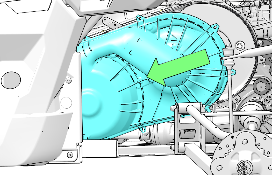
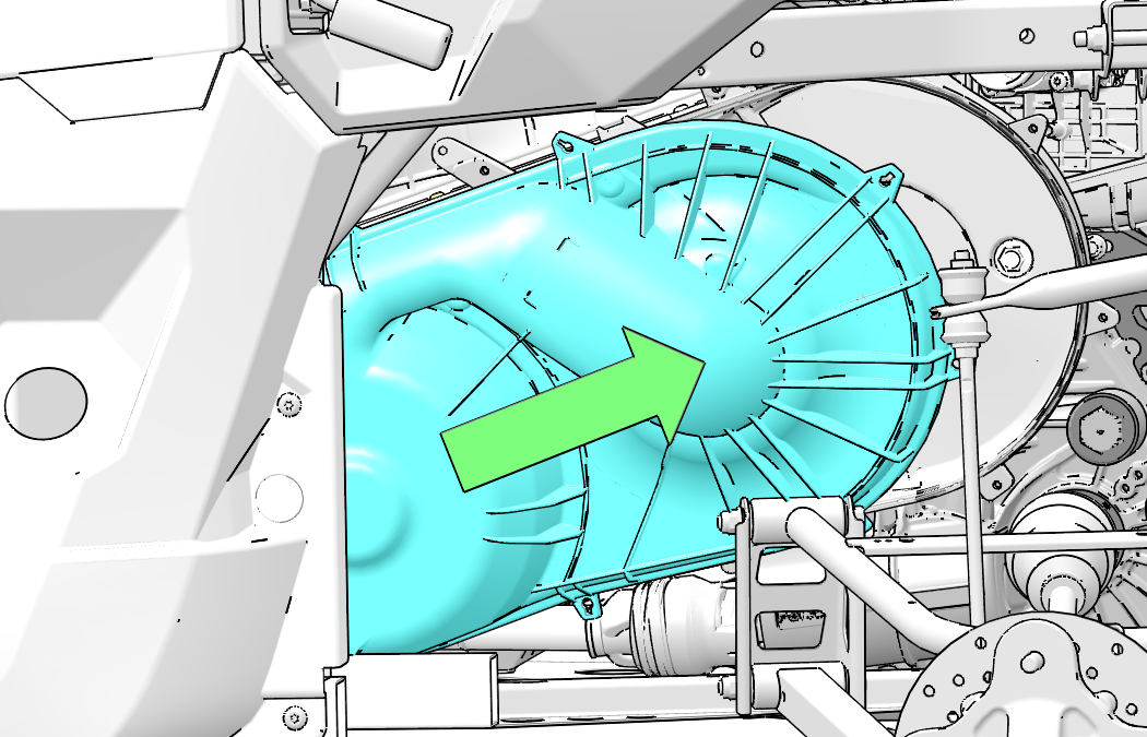
  2. Pull the clutch cover forward and slide towards the front of the vehicle as shown above.
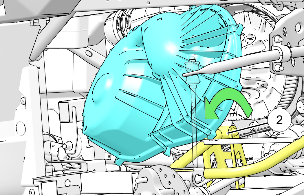
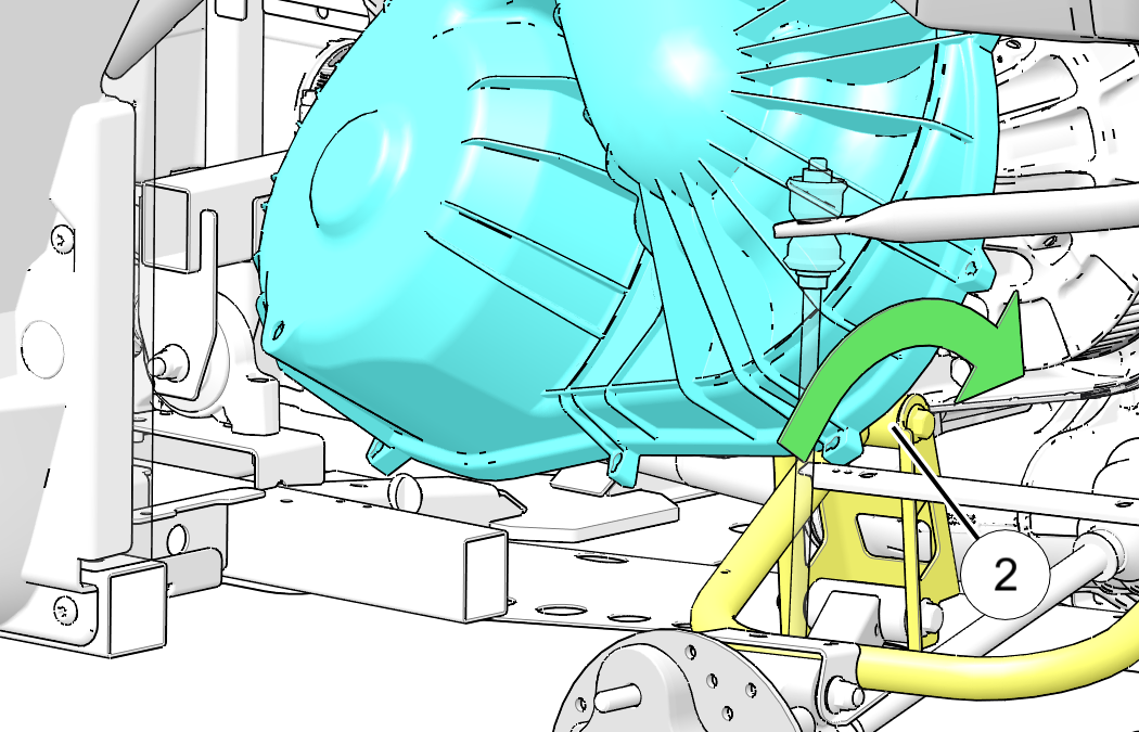
  3. Rotate the clutch cover back and lift up and over the control arm mounting .
    NOTE
    Use care when lifting clutch cover upwards. Do not damage cover, intake boot, or electrical harness.

    Image

    Image
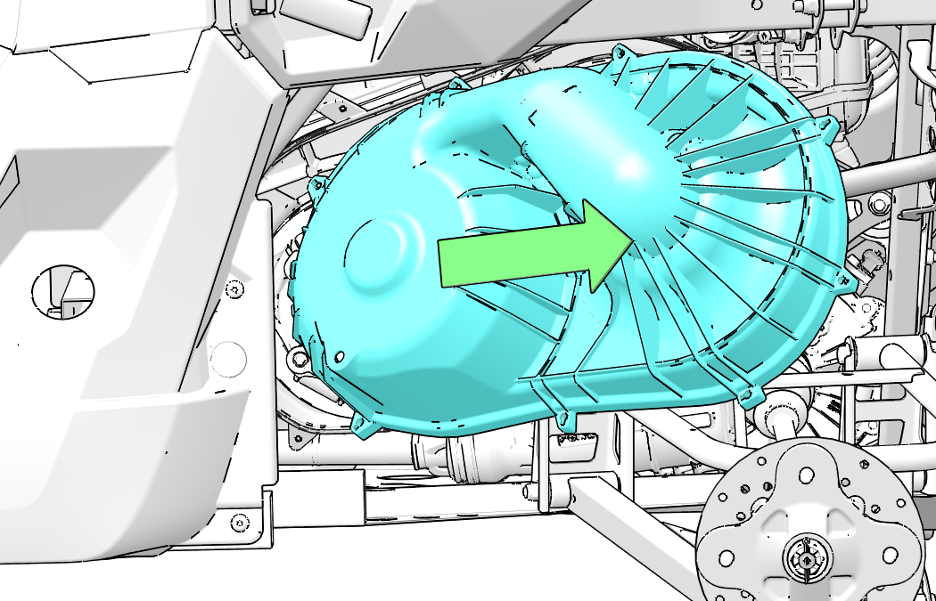
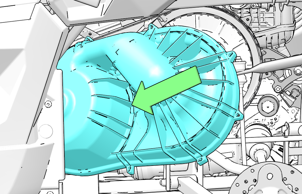
  4. Pull clutch cover out towards the rear of the vehicle as shown above.
  5. Mark the drive belt direction of rotation so that it can be installed in the same direction.
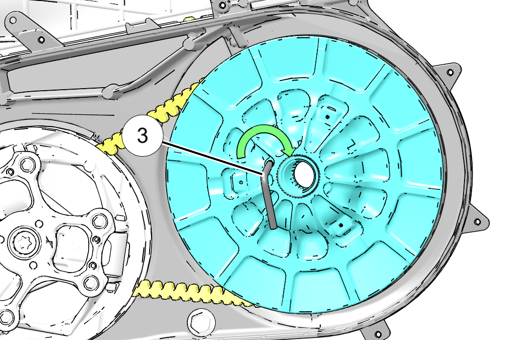
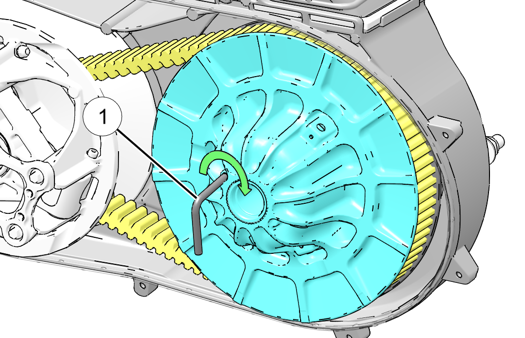
  6. Insert clutch spreader tool into threaded hole on driven clutch as shown and turn clockwise to spread clutch.

    NOTE

    Clutch spreader tool part number 2875911 is found in vehicle tool kit.

    Image
  7. Walk the belt out of the driven clutch and drive clutch. Remove the belt from the vehicle.

Belt Inspection

To inspect the drive belt, do the following:
  1. Inspect belt for hour-glassing (extreme circular wear in at least one spot and on both sides of the belt). Hour glassing occurs when the drive train does not move and the drive clutch engages the belt.
  2. Inspect belt for loose cords, missing cogs, cracks, abrasions, thin spots, or excessive wear. Compare belt measurements with a new drive belt. Replace if necessary.
  3. Belts with thin spots, burn marks, etc., should be replaced to eliminate noise, vibration, or erratic PVT operation.

Belt Installation

NOTE
Be sure to install belt in the same direction as it was removed.
  1. With the clutch spreader tool installed, loop the belt over the drive clutch and over the driven clutch.

    Image

    Image
  2. Rotate the driven clutch and walk the belt into the clutch.
  3. Remove the clutch spreader tool from driven clutch.
  4. Rotate / spin the driven clutch and belt approximately 5-7 times to properly seat the belt in the driven clutch.
  5. Install the clutch cover into wheel well as shown above.
  6. Rotate clutch cover over A-Arm as shown below. Use care not to damage intake boots or electrical harness.
  7. Pull clutch cover backwards and align with bolt holes on inner clutch cover as shown below.

    Image

    Image
  8. Install and torque the outer clutch cover bolts to specification.Image
    TORQUE

    PVT Outer Cover Fasteners

    35 in-lbs (4 Nm)


© Copyright Polaris Industries Inc. All rights reserved.