Content Source: 2020 Timbersled ST 93 Ripper Owner’s Manual (9929952 01) > Installation Chapter

IMPORTANT

The Owner's Manual for this vehicle contains warnings, instructions and other information you must read and fully understand before safely riding or performing maintenance on this vehicle.Always follow the warnings and instructions in Owner's Manual.

Click the CONTENTS link above for the Table Of Contents, or download a full PDF of the Owner Manual in the Owner Support area of Polaris.com

Installation Instructions

NOTE
All directions in the Installation Instructions section, such as Left and Right, are referenced from the position of a rider sitting on the motorcycle

Motorcycle Disassembly

NOTE
The disassembly process listed is universal for all bikes using the ST 93 Ripper kit. This process may vary slightly between makes and models. Refer to your host motorcycle owner’s manual for specific references and disassembly procedures.
  1. Place motorcycle on a stand or suitable support where both wheels are off the ground. Secure properly to prevent bike from tipping when wheels are removed.(An adjustable stand is helpful for reassembly.)
  2. Remove the seat and side panels.
  3. Remove chain by disconnecting master link.
  4. Remove the rear brake lever from frame and let hang (this includes the spring).
  5. Remove upper rear shock bolt or pin.
    NOTE

    Keep upper shock bolt for later use as this item will be reinstalled.

  6. Remove the rear swing arm bolt (this will drop the entire swing arm assembly off the motorcycle) and remove the shock, tire, brake, and swing arm assembly from the motorcycle as a complete unit.
    NOTE

    It is recommended to cable tie all bushings, spacers, etc. to their corresponding parts at all pivoting points to prevent losing any parts during storage.

  7. Remove the front brake lever and cable retainer bolts from the front forks. (On some models use the provided cable tie to secure start button).
  8. Loosen the front axle bolt and remove the front wheel.
    NOTE

    Keep front axle bolt for later use, this item will be reinstalled.

  9. Remove the front drive sprocket and sprocket cover.
  10. Check to ensure all previous steps are complete, before moving on to the Rear Ripper Assembly instructions.

Rear Ripper Assembly

SWING ARM SPACER APPLICATION


Left Side

Right side

Spacer Spec.

Part #

Spacer Spec.

Part #

Honda

0.80 mm

5141218

6.87 mm

5141219

Kawasaki

N/A

N/A

N/A

N/A

Yamaha

N/A

N/A

15 mm

5141220

*Left and Right referenced from the position of a rider sitting on the bike

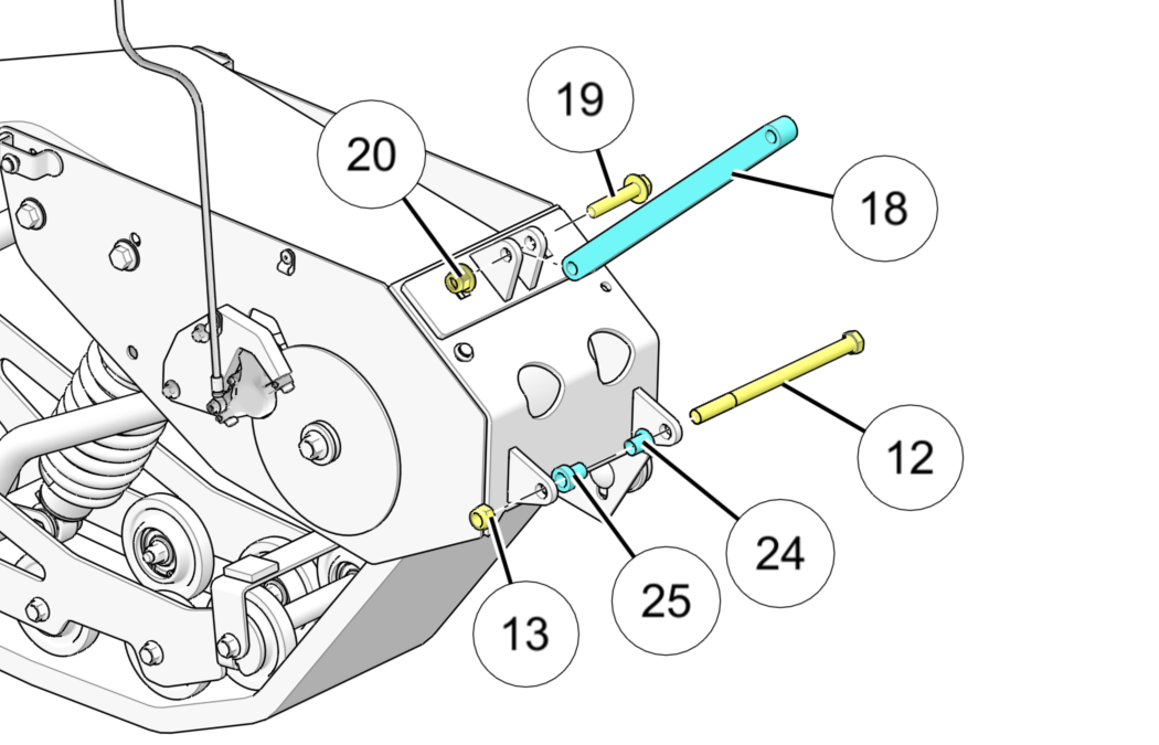
  1. Position the Ripper rear track assembly up to the rear swing arm bolt location on the bike. Some fit kits will require spacers / on one or either side of the frame, located between the Ripper frame mount brackets and the bike’s swing-arm bolt bracket location. See the Swing Arm Spacer Application table at the beginning of this section for specific bike model spacers and locations.
    NOTE

    Kawasaki KLX models do not require any spacers. Honda CRF models require left and right swing arm bolt spacers/reducers. Yamaha TTR models require a single spacer positioned on the right side of the bike frame.

  2. Slide provided 7/16” x 6-1/2” swing arm bolt in from the left hand side of the motorcycle and tighten lock nut to listed torque specification.
    TORQUE

    54 Nm (40 Ft. Lbs)

    Image
  3. Move on to complete the Strut Rod Installation instructions.
    NOTE

    Read carefully to ensure you complete the proper Strut Rod Installation steps for your specific motorcycle brand.

HONDA & YAMAHA MODELS: Strut Rod Installation

  1. See note below before continuing.
    NOTE

    The following instructions are for HONDA and YAMAHA MODELS ONLY.

    Bolt the lower portion of the strut rod to the rear Ripper assembly using the provided bolt and locknut . DO NOT TIGHTEN (i.e. torque) the lower portion of the strut rod until the upper portion has been bolted in place.
  2. Bolt the upper portion of the strut rod into the motorcycle’s upper shock bracket using the bike’s upper shock mount bolt or pin. For motorcycles using a bolt, torque to your specific motorcycle manufacturer’s specifications.Image
  3. Once you have the upper portion of the strut rod in place, torque the lower portion of the strut rod to the following specification.
    TORQUE

    60 Nm (44 Ft. lbs)

  4. Move on to complete the Brake Line Assembly and Routing instructions.
    NOTE

    Read carefully to ensure you complete the proper Brake Line Assembly and Routing steps for your specific motorcycle brand.

KAWASAKI MODELS: Strut Rod Installation

  1. See note below before continuing.
    NOTE

    The following instructions are for KAWASAKI MODELS ONLY.

    Bolt the lower portion of the strut rod to the rear Ripper assembly using the provided bolt and locknut . DO NOT TIGHTEN (i.e. torque) the lower portion of the strut rod until the upper portion has been bolted in place.
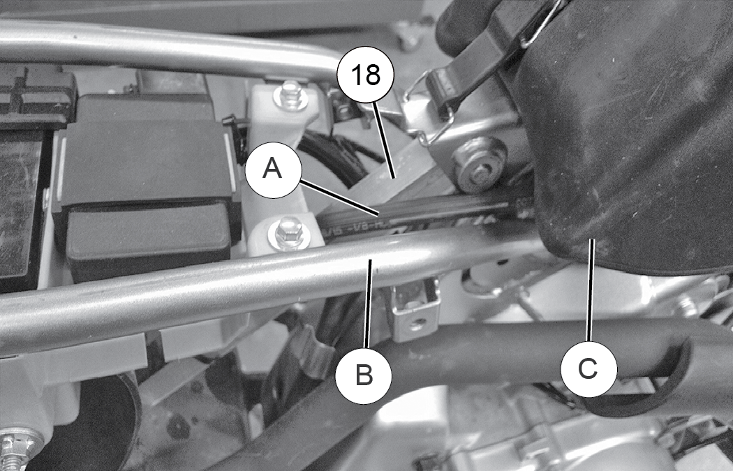
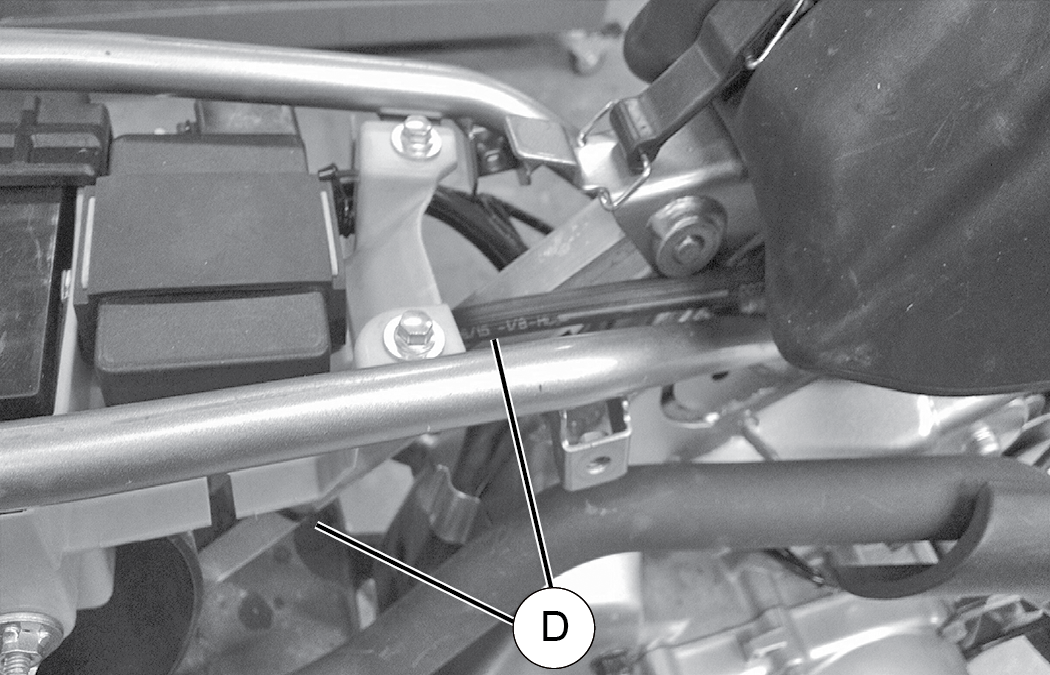
  2. Before you fasten the upper strut rod bolt, move the strut rod up to provide enough clearance to feed the brake line and master cylinder over the top of the rear right sub-frame tubing of the motorcycle and under the gas tank as seen in the image below.
  3. Move the top of the strut rod back down into position, lining up the mounting holes. Bolt the top of the strut rod in place using the original upper strut rod bolt or pin and torque to your specific motorcycle manufacturer’s specifications. Image
  4. Once you have the upper portion of the strut rod in place, torque the lower portion of the strut rod to the specification listed below.
    TORQUE

    60 Nm (44 Ft. Lbs)

  5. Move on to complete the Brake Line Assembly and Routing instructions.
    NOTE

    Read carefully to ensure you complete the proper Brake Line Assembly and Routing steps for your specific motorcycle brand.

Brake Line Assembly and Routing

WARNING
When routing brake lines it is critical that you keep all brake lines away from any surfaces, such as engine or exhaust, that can become hot while operating the vehicle. Failure to comply will adversely affect the vehicles brake system and may lead to severe injury or death.
NOTE
All images in theBrake Line Assembly and Routing section show a Honda model and are provided for reference ONLY.

Kawasaki Models: Brake Line Assembly and Routing

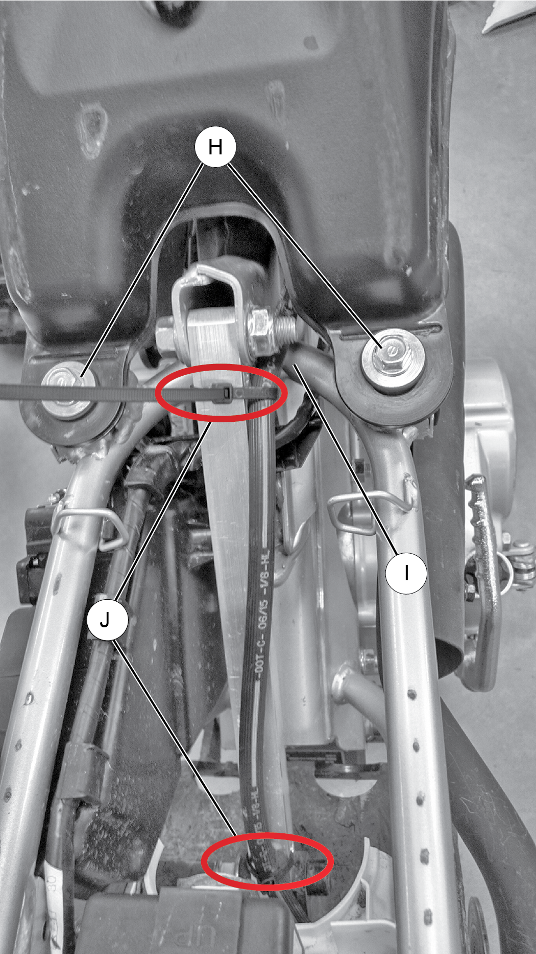
  1. Prevent slack in the brake line while fastening the brake line to the top and the bottom of the strut rod with provided cable ties in the locations indicated in the image below. Image
  2. Run the brake line forward under the bottom of the gas tank along the main frame of the bike towards the bike’s front neck-tube. Make sure there is a minimum of one inch of clearance between the brake line and the lower head set turning stop posts to prevent the brake line from being pinched.
  3. Place another cable tie around the brake line fastening it to the bike’s throttle cable keeper bracket . The remaining brake line can free hang up to the master cylinder mounted on the right handle bar.
  4. Adjust the pitch of the brake lever, ensuring it is easily reached and easy to pull.
  5. Tighten the brake lever perch hand tight being careful to not strip the mounting perch threads. If needed, you can loop any remaining slack in the brake line in between the right fork tube upper and the neck-tube of the bike frame as seen in the photo below. (Honda model shown for reference).
    WARNING

    When routing brake lines, make sure there is a minimum of one inch of clearance between the brake line and the lower head set turning stop posts to prevent the brake line from being pinched. Failure to comply will adversely affect the vehicles brake system and may lead to severe injury or death.

    Image
  6. Ensure all previous steps are complete. Then move on the Drive Chain and Sprocket Assembly instructions.

Yamaha Models: Brake Line Assembly and Routing

  1. For the Yamaha TTR models, either run the brake line forward on top of the strut rod or run the break line parallel and against the left hand side of the strut rod.
  2. Secure the brake line to the strut rod with a cable tie located at the top of the strut rod and one at the bottom of the strut rod in a similar fashion to the photo for the Honda model.
  3. Then feed the brake line and master cylinder to the right side of the motorcycle feeding the brake line between the bike’s upper sub-frame column and the wiring harness brackets on the frame. This will help hold the brake line against the bikes frame and as far away from the exhaust system as possible.
  4. Finally, route the brake line forward towards the front of the motorcycle underneath the motorcycle’s fuel tank. Place another cable tie near the front of the bike securing the brake line to the bikes lower horizontal frame tube.
    WARNING

    When routing brake lines, make sure there is a minimum of one inch of clearance between the brake line and the lower head set turning stop posts to prevent the brake line from being pinched. Failure to comply will adversely affect the vehicles brake system and may lead to severe injury or death.

    Image
  5. Ensure all previous steps are complete. Then move on to the Drive Chain and Sprocket Assembly instructions.

Honda Models: Brake Line Assembly and Routing

  1. Remove the two rear gas tank bolts and loosen the front tank bolt on the bike. Lift up on the rear of the gas tank giving yourself enough room to feed the brake line and master cylinder over top of the rear right sub-frame tubing of the bike and under the gas tank as indicated in the image
  2. Feed the brake line forward under the bottom of the gas tank along the main frame of the bike.
  3. Keeping all of the slack out of the brake line fasten the brake line to the top and the bottom of the strut rod with cable ties as shown .
  4. Reinstall the two rear gas tank bolts previously removed and torque to bike manufacturers specification.
  5. Next, torque the front tank bolt to manufacturers specifications. See image for brake line routing reference .

Image
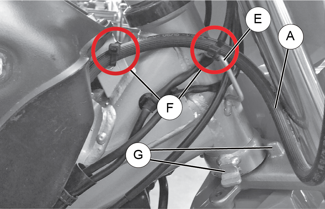
  1. Near the front of the bike where the brake line is approaching the front neck tube of the bike, cable tie the brake line to the front gas tank frame mount and another cable tie to the bikes frame-mounted wire harness on the bike’s neck tube. See photo below for cable tie locations .
  2. The remaining brake line can free hang up to the master cylinder mounted on the right handle bar.
  3. Adjust the pitch of the brake lever, ensuring it is easily reached and easy to pull.
  4. Tighten the brake lever perch hand tight being careful to not strip the mounting perch threads.
    WARNING

    When routing brake lines, make sure there is a minimum of one inch of clearance between the brake line and the lower head set turning stop posts to prevent the brake line from being pinched. Failure to comply will adversely affect the vehicles brake system and may lead to severe injury or death.

    Image
  5. Ensure all previous steps are complete. Then move on to the Drive Chain and Sprocket Assembly instructions.

Drive Chain and Sprocket Assembly

  1. Install provided sprocket onto motorcycle transmission output shaft.
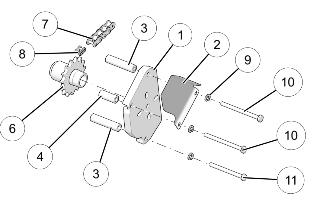
  2. Place backer plate spacers / and chain guard into position on the backer plate as shown and start bolts/ with lock washers as shown to hold spacers and chain guard in position.
    IMPORTANT

    Reference your specific install kit’s content image, starting on page Kit Contents, for spacer/ and bolt/ locations as they vary per kit. Make sure to use Blue Loctite® 243 on the provided 3 button head screws /.

  3. Next, slide backer plate, spacer and chain guard assembly onto the transmission output shaft and into position.
  4. Tighten the sprocket backer plate to the engine case and torque to bike manufacturer’s specifications before chain is installed and chain tension is set.
    NOTE

    Reference you host bike owner’s manual or manufacturer’s specifications for proper torque specifications.

    Image
  5. Route chain around both front and rear sprockets.
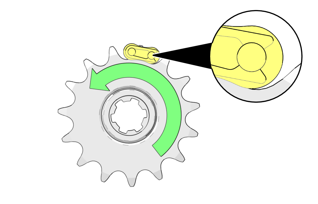
  6. Complete the assembly of the chain with the master link provided. Be sure to install the master link with the opening of the link facing rearward in relation to the chain direction as shown. Image
  7. Set the proper chain tension by loosening chain slider nut and bolt. Slide the chain slider up or down until 1/2”-5/8” of vertical deflection is met in the upper chord of the drive chain. Torque chain slider nut to specification below when proper tension is achieved.
    TORQUE

    25 Nm (18 Ft. Lbs)

    NOTE

    The chain will stretch within the first 5hrs. You MUST check for proper chain tension after this initial break-in period and readjust as necessary. The chain slider is not intended to roll and can be rotated as needed to keep proper chain tension on the usable surface of slider.

  8. After completing the previous steps, move on to Front Ski and Spindle Assembly instructions.

Front Ski and Spindle Assembly

SPINDLE SPACER APPLICATION
 

Left Side

Right side

RDCR Spec.

Part #

RDCR Spec.

Part #

Honda

18.03 mm

5141390

25.4 mm

5141389

Kawasaki

17.35 mm

5141392

17.35 mm

5141392

Yamaha

14.91 mm

5141394

20.49 mm

5141393

*Left and Right referenced from position of a rider sitting on the bike

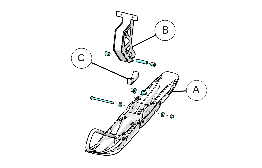
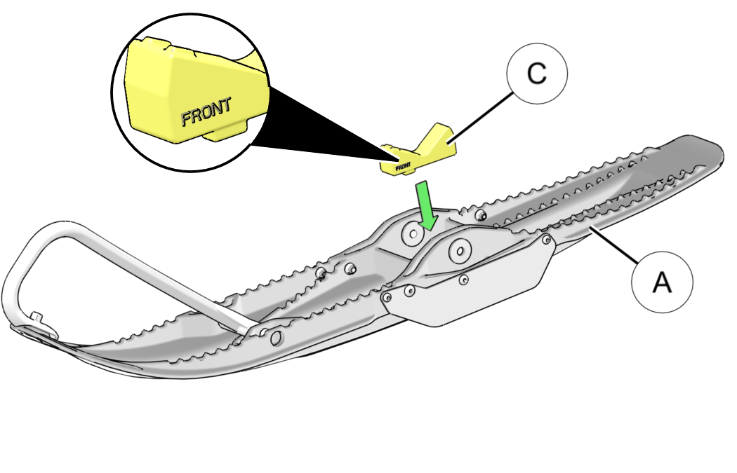
  1. Locate the front ski , spindle , ski rubber , and provided hardware.Image
  2. Place the Ski Rubber on top of the center of the ski with the indicated “Front” of the Ski Rubber towards the front tip of the Ski.Image
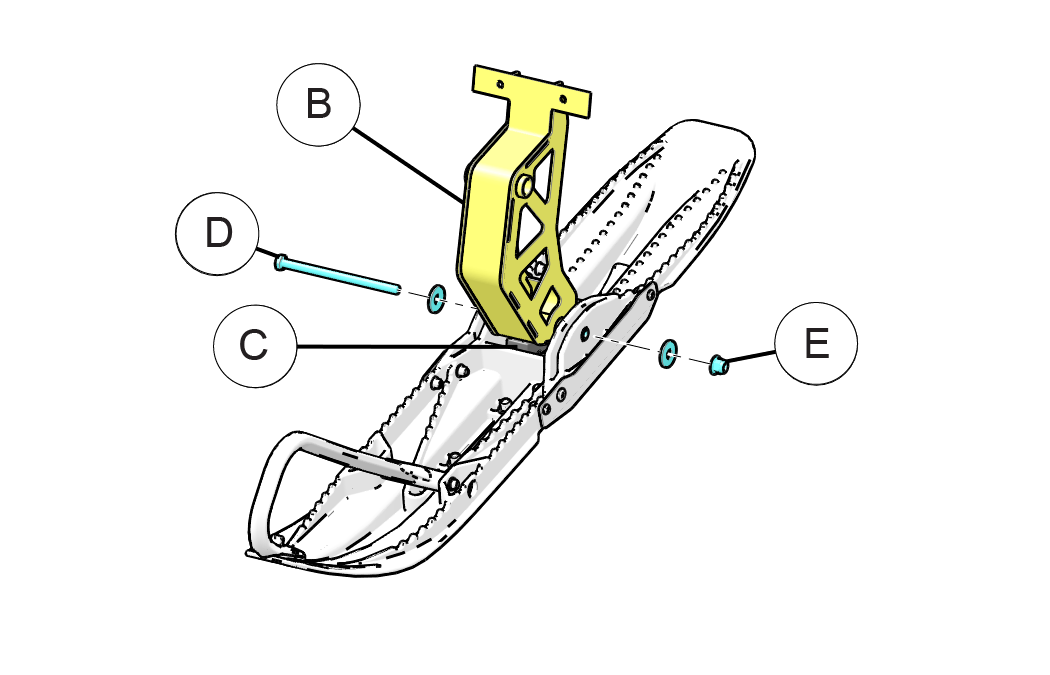
  3. Place the lower portion of the Spindle on top of the Ski Rubber in the ski saddle as shown in the image below. Line up the bottom bolt hole and insert the M 10 x 155 mm bolt and install the nut onto the bolt. Then torque to specification listed below.
    TORQUE

    45 Nm (33 Ft. Lbs)

    Image
    WARNING

    Failure to torque fasteners as directed will adversely affect the steering system and may lead to severe injury or death.

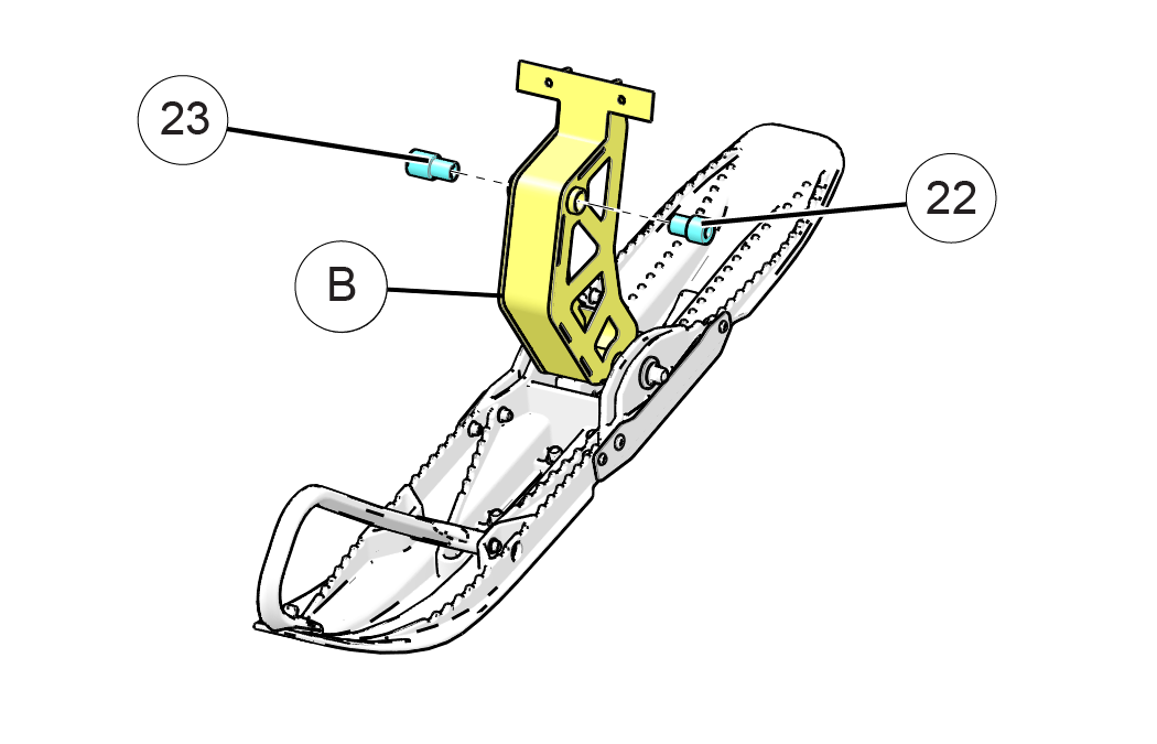
  4. Insert front spindle reducers / onto the spindle . Your motorcycle model’s ST 93 Ripper Installation Kit will come with the appropriate spindle reducers/spacers for your motorcycle make and model. See the table entitled, Spindle Spacer Application, at beginning of this section for spindle reducer placement for your specific motorcycle model.Image
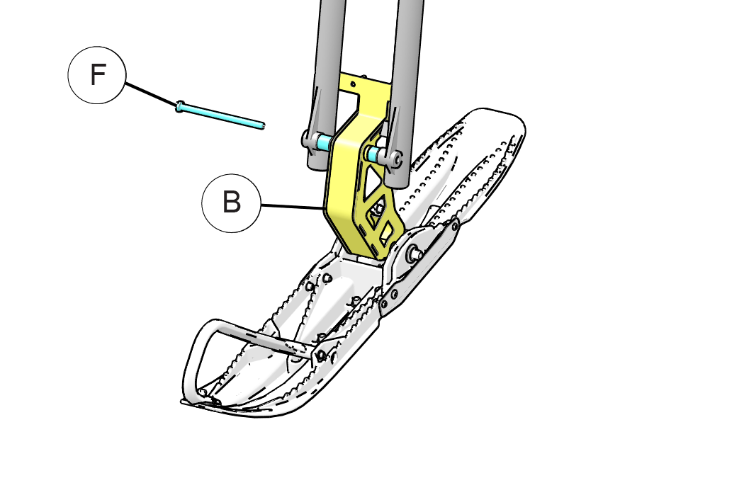
  5. Use the existing front axle bolt to attach the front spindle to the forks . DO NOT TIGHTEN the front axle bolt yet. The front axle bolt can be snug, but should not be fully tightened until you complete step 6.Image
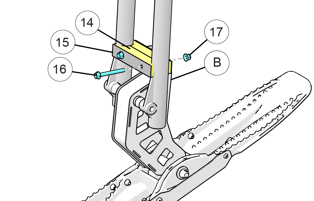
  6. Using the composite fork clamp (fork clamp halves are identical), place one half of the fork clamp in front of the fork tubes with the concave portions resting against the front side of the fork tubes (just above the spindle). Take the other half and mate it around the back side of the fork tubes, but in front of the spindle’s backer plate. This will result in the fork tubes positioned between the two fork clamp halves withand the spindle’s backer plate positioned between the two fork clamp halves.
  7. Take the fork clamp washer plate and place it over the face of the front fork clamp lining up the bolt holes of the washer plate with the clamp.
  8. Using the two provided fork clamp bolts supplied with your kit, insert each bolt through one of the two bolt holes (see image below). Each bolt will run through the washer plate, front and back fork clamp halves, and finally through the spindle backer plate. To hold the fork clamp assembly together, apply the supplied M8 locking nuts and torque to specification listed below.
    TORQUE

    20 Nm (15 Ft. Lbs)

    Image
  9. Finally, tighten the front axle bolt .
    IMPORTANT

    Refer to manufacturer’s specifications for the front axle bolt’s proper torque setting.

  10. Check to ensure all previous steps are complete. Then move on to the Rear Cowling Assembly instructions.

Rear Cowling Assembly

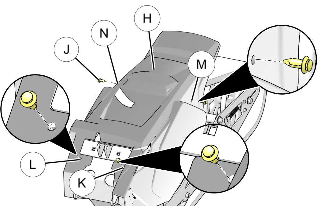
  1. To install the rear cowling with the four provided nylon rivet fasteners, first slide the cowling forward under the motorcycle’s rear fender. Ensure the front left chain guard portion of the cowling is positioned behind the drive sprocket plate, and ensure the front mounting holes of the skid frame line up with the front mounting holes of the rear cowling. Image
  2. Then insert a nylon rivet fastener securely into the front left side mounting hole . Repeat this process for the front right side mounting hole .
    NOTE

    The rear cowling is pliable, the easiest process for lining up the rear fastener mounting holes of the skid frame with the cowling holes is to pull out on the bottom most part of the cowling in the middle of the molding. This will pull the rear hole in the cowling forward allowing you to line up the holes to insert the nylon rivet fasteners.

  3. Repeat this process for both the left and then the right rear mounting holes.
  4. This completes the ST 93 Ripper installation process. Check to ensure all tools and parts are accounted for and all steps have been completed in the proper order.

© Copyright Polaris Industries Inc. All rights reserved.