
Content Source: 2020 GENERAL 1000 Owner’s Manual (9929901 R01) > Features and Controls Chapter
| IMPORTANT |
|
The Owner's Manual for this vehicle contains warnings, instructions and other information you must read and fully understand before safely riding or performing maintenance on this vehicle.Always follow the warnings and instructions in Owner's Manual. Click the CONTENTS link above for the Table Of Contents, or download a full PDF of the Owner Manual in the Owner Support area of Polaris.com |
| Gear Indicator | This indicator displays gear shifter position. H = High Gear L = Low Gear N = Neutral R = Reverse Gear P = Park -- = Gear Signal Error (or shifter between gears) |
|
| AWD Indicator | This indicator shows whether 2X4 or AWD is active. | |
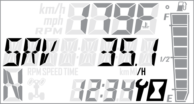
| Service Indicator | A flashing wrench symbol alerts the operator that the preset service interval has been reached. Your POLARIS dealer, or other qualified person, can provide scheduled maintenance. See Programmable Service Interval for resetting instructions. | |
| Fuel Gauge | The segments of the fuel gauge show the level of fuel in the fuel tank. When the last segment clears, a low fuel warning is activated. The outline of the fuel display will flash. Refuel immediately. | |
| Speed Limitation (if equipped) | This vehicle may be equipped with a maximum speed limitation function. This would be displayed on the screen as “LIM” followed by the speed. “LIM 30” for example. |
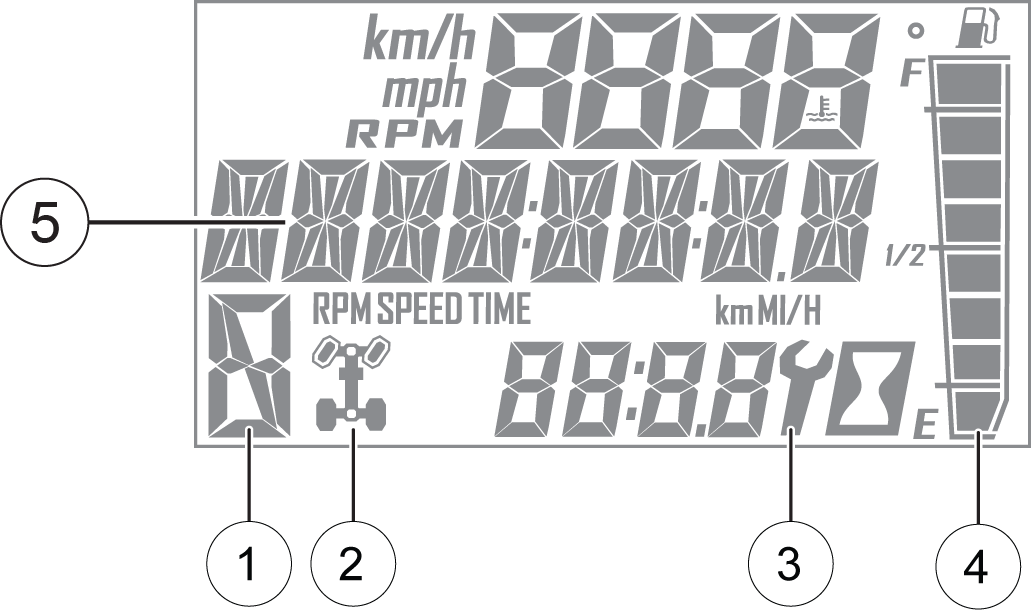
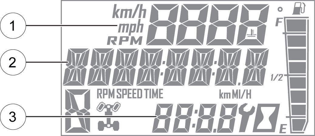
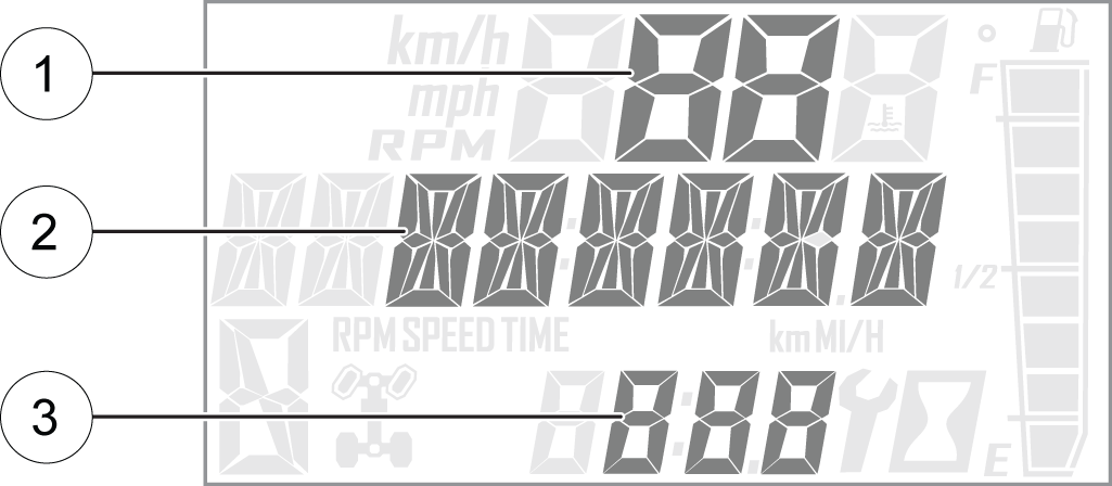
The rider information center contains three areas that display mode information.
| Description | |
| Engine Temperature | Temperature of engine coolant |
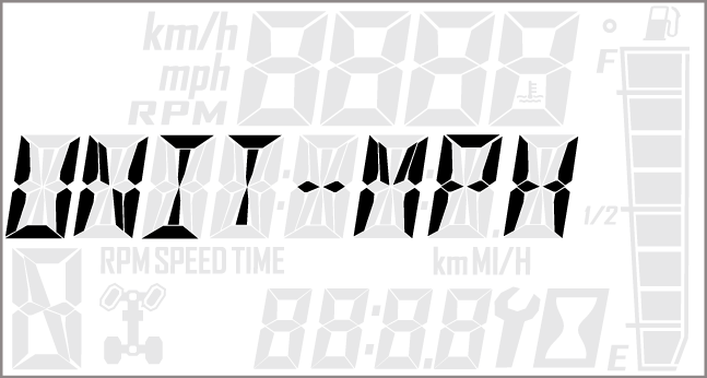
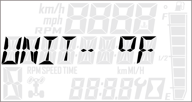
| Vehicle Speed | Speed of vehicle |
| Tachometer | Engine speed (RPM) |
| Description | |
| Odometer | The odometer records and displays the distance traveled by the vehicle. |
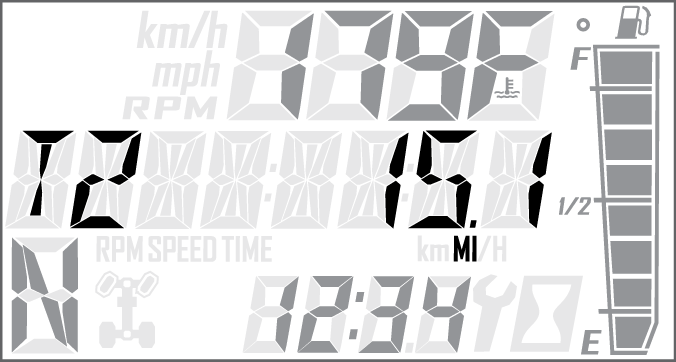
| Trip Meters (T1/T2) | A trip meter records the distance traveled by the vehicle if reset before each trip. To reset, see Trip Meter. |
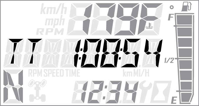
| Engine Hours | Total hours of engine operation since manufacture |
| Service Hours | A flashing wrench symbol indicates that the preset service interval has been reached. To reset, see Programmable Service Interval. |
| Trip Time | Time length of vehicle operation since mode was last reset |
| Description | |
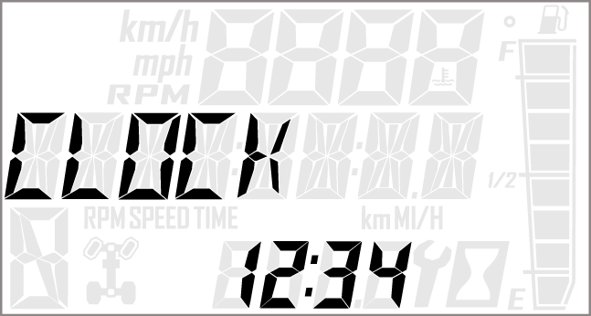
| Clock | The clock displays time in a 12-hour or 24-hour format. To reset, see Clock. |
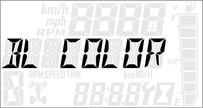
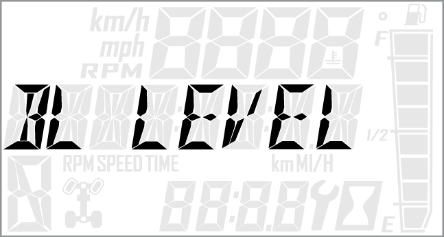
The information center backlight can be set to either blue or red.
Use a trip meter to track the distance traveled during a specific trip or period of time. Reset the meter to zero before traveling.
Use a trip time meter to track the travel time during a specific trip. Reset the meter to zero before traveling.
| NOTE |
| If the displayed code is an engine fault code, the CHECK ENGINE lamp will blink. If the displayed code is an EPS fault code, the EPS lamp will blink. |
© Copyright Polaris Industries Inc. All rights reserved.