Content Source: 2020 550 Indy 144 Owner’s Manual (9929781 R01) > Maintenance Chapter
| IMPORTANT |
|
The Owner's Manual for this vehicle contains warnings, instructions and other information you must read and fully understand before safely riding or performing maintenance on this vehicle.Always follow the warnings and instructions in Owner's Manual. Click the CONTENTS link above for the Table Of Contents, or download a full PDF of the Owner Manual in the Owner Support area of Polaris.com |
| If you become aware of higher than normal clutch engagement or an unusual vibration or shift pattern, see your dealer or qualified person immediately. Do not operate the snowmobile until repairs have been made. |
| NOTICE |
| The slider blocks and bushings of the 550 clutches are made of a material that may be damaged if lubricated. Do not lubricate bushings or slider blocks. |
|
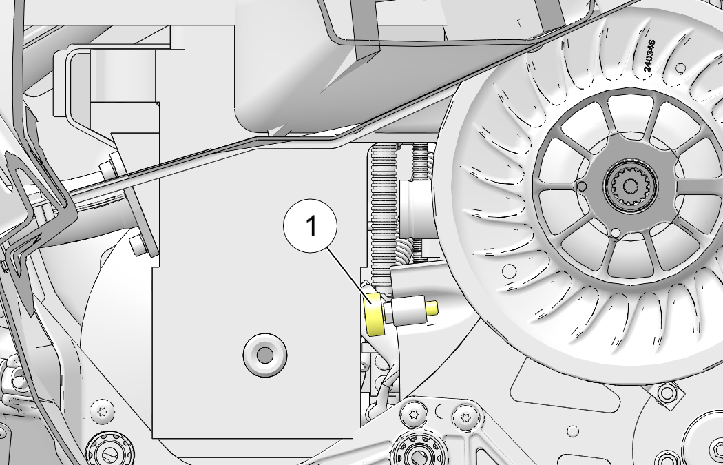
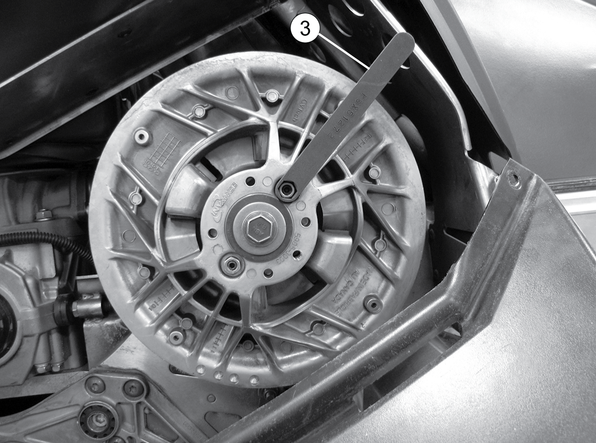
Belt Tension Adjuster
Tool
PN: PS-51272 |
| NOTE |
|
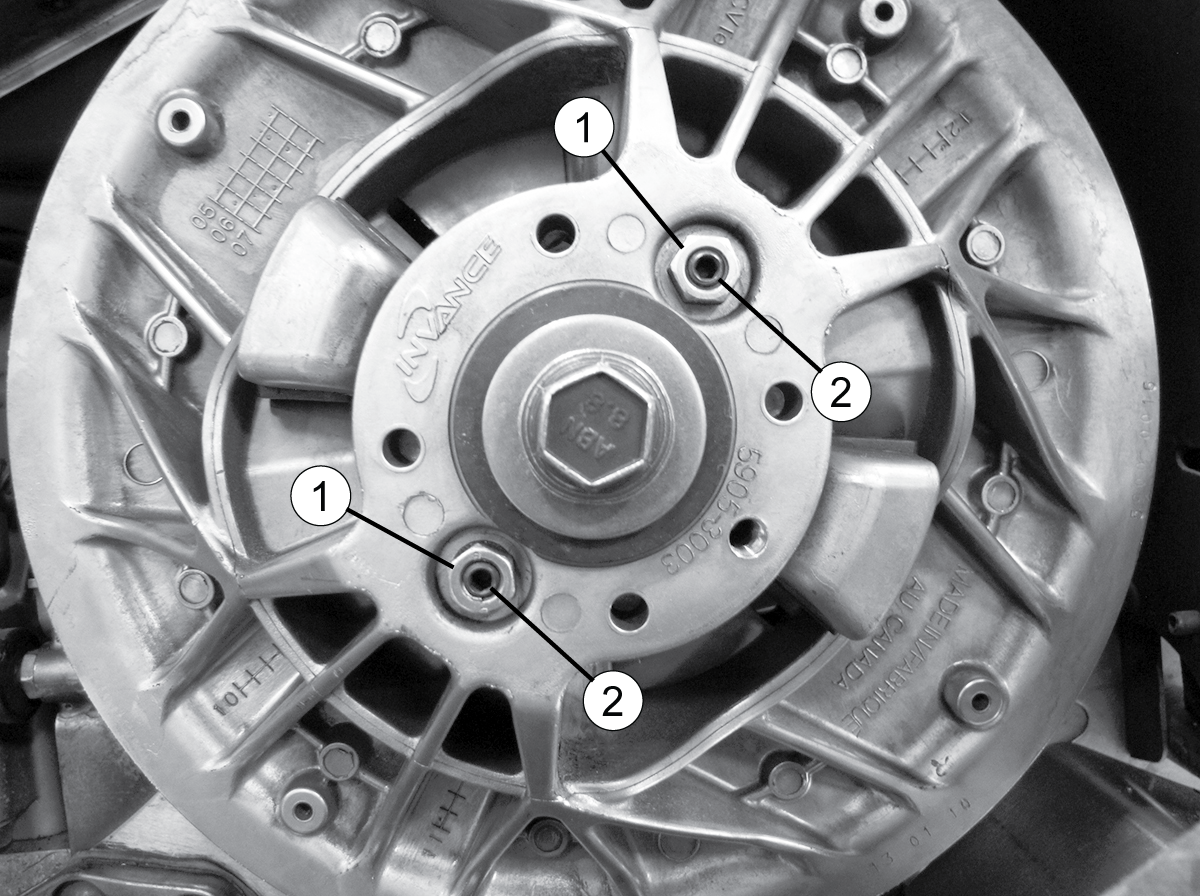
Both adjuster screws will need to be turned outwards (counter-clockwise) to decrease deflection. When making adjustments, only adjust one of the screws. |
|
Drive Belt Deflection 1 1/8 - 1 1/4 in. (2.85 - 3.2 cm) |
| TORQUE | |
|
Driven Clutch Adjustment Screw Jam Nuts: 57.5 - 75 in-lbs (6.5 - 8.5 Nm) |
| NOTICE |
|
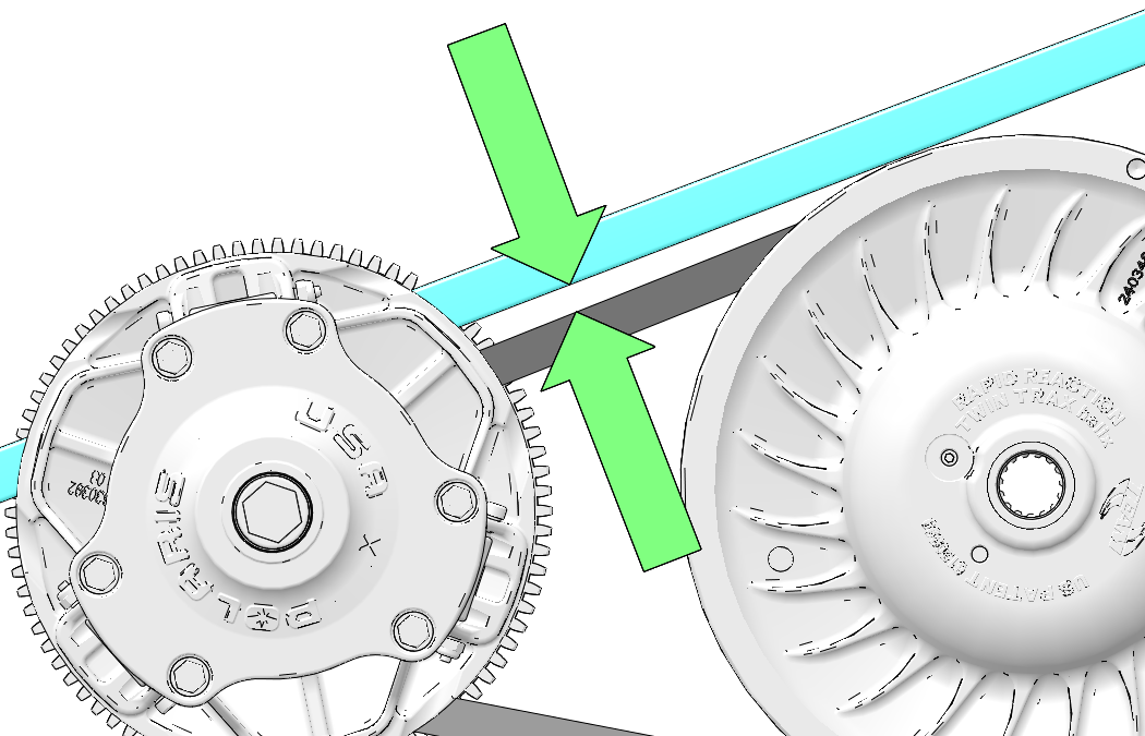
Do not attempt to remove the drive belt after operating
in reverse. The snowmobile must be stopped after forward motion to
prevent damage to components
during belt removal. Rotate the driven clutch counter-clockwise 1/4
turn by hand to ensure forward
engagement before attempting
to remove the belt.
|
| TIP |
|
Install the belt so that the numbers can be read correctly on the left side of the vehicle, or in the direction in which the belt was originally installed. |
© Copyright Polaris Industries Inc. All rights reserved.