Content Source: 2020 RUSH / SWITCHBACK / Pro-S / XCR Owner’s Manual (9929780 R02) > The Perfect Fit Chapter
| IMPORTANT |
|
The Owner's Manual for this vehicle contains warnings, instructions and other information you must read and fully understand before safely riding or performing maintenance on this vehicle.Always follow the warnings and instructions in Owner's Manual. Click the CONTENTS link above for the Table Of Contents, or download a full PDF of the Owner Manual in the Owner Support area of Polaris.com |
| IMPORTANT |
|
Moving a handlebar component without first loosening
its screws/set screws may cut grooves into the handlebar, making it
difficult
to secure the component.
Do not move a handlebar component without first loosening its mounting
screws/set screws. Take care
to avoid damaging hand
warmer/brake switch wires when moving components.
|
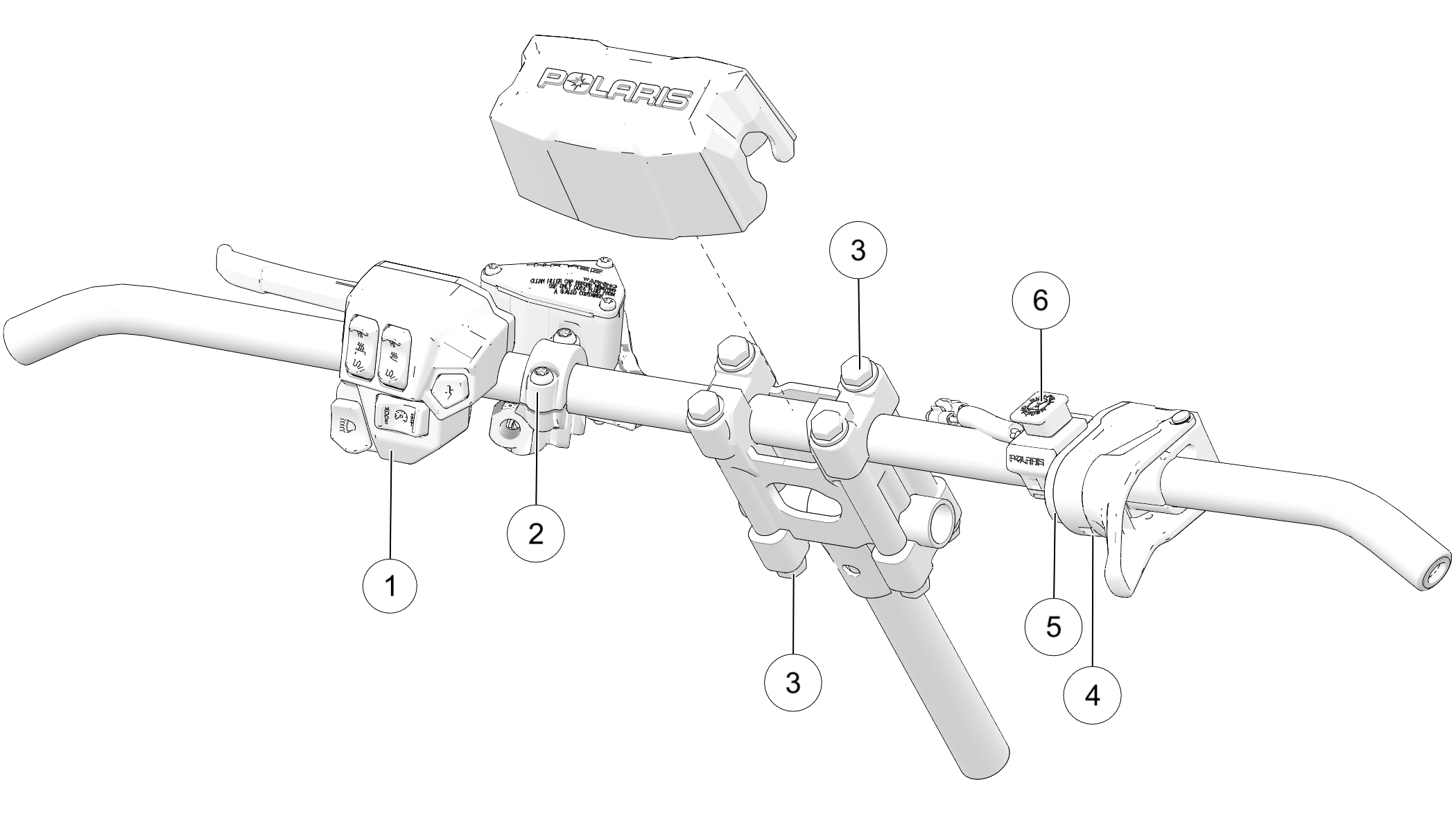
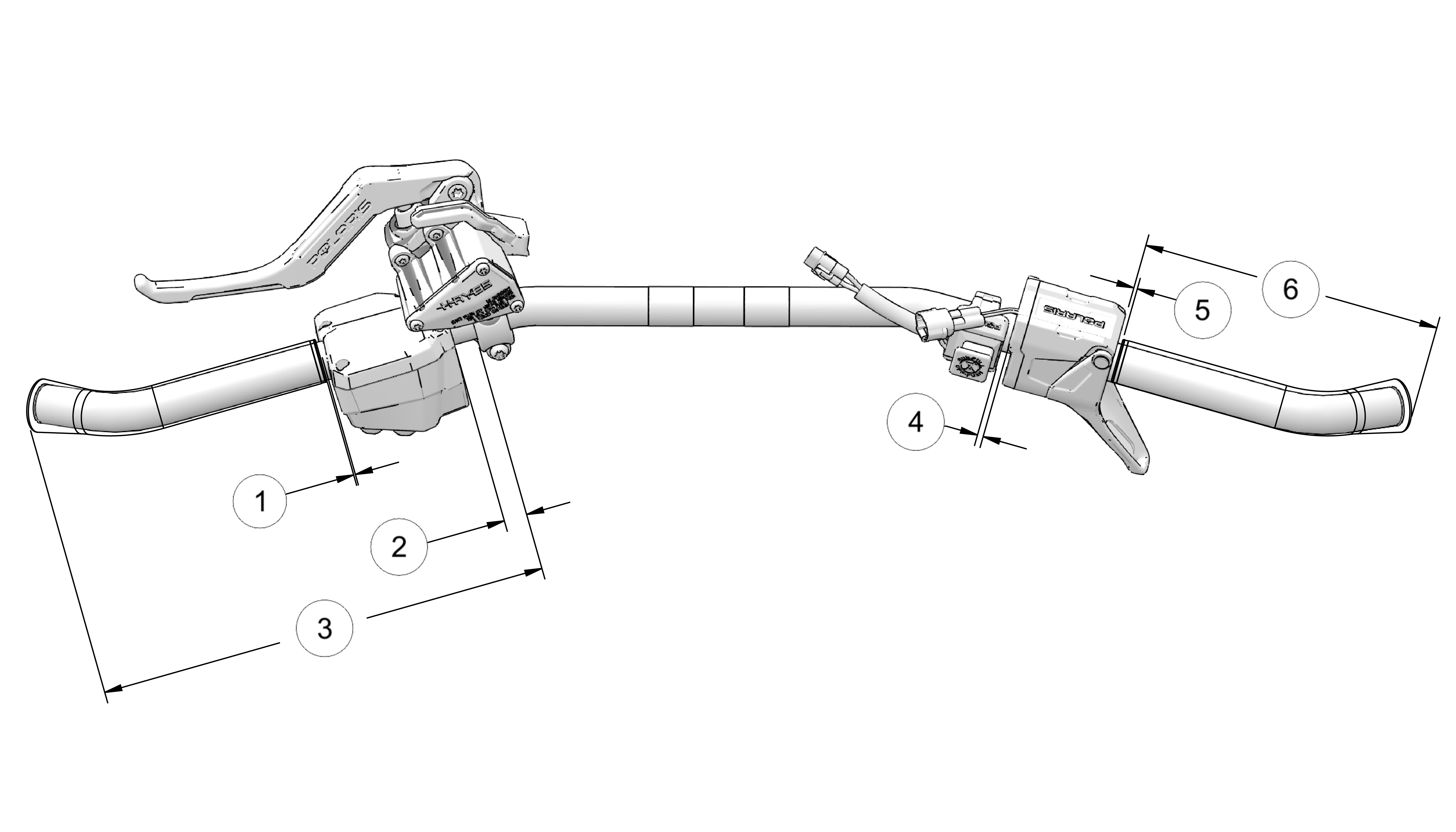
| Component | Torque DO NOT OVER-TIGHTEN |
|
|---|---|---|
| Left Handlebar Control Block | 20 in-lbs (2.3 Nm) | |
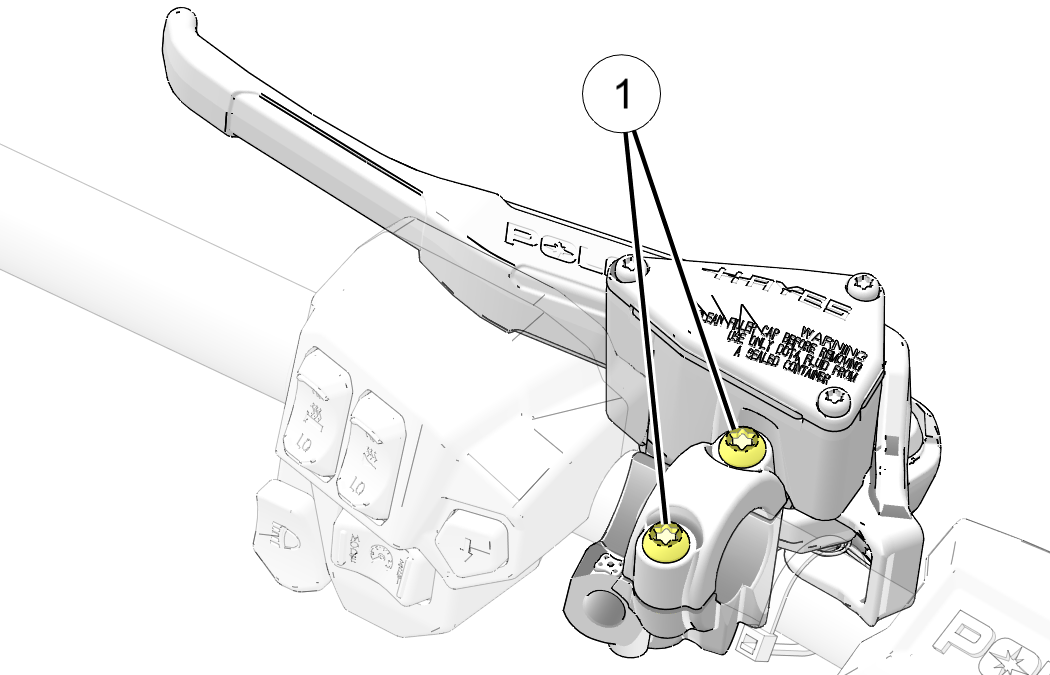
| Brake Lever / Master Cylinder Torque the front screw first, then torque the screw next to the reservoir. |
70 in-lbs (7.9 Nm) | |
| Upper / Lower Riser Clamps | 14.8 ft-lbs (20 Nm) | |
| Throttle Lever Block Set Screw | 27 in-lbs (3.1 Nm) | |
| Throttle Lever Block Cover Screws | 6 in-lbs (0.7 Nm) | |
| Auxiliary Engine Stop Switch Set Screw | 12 in-lbs (1.4 Nm) | |
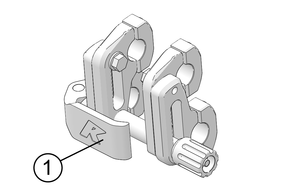
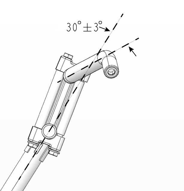
| Riser | Install with the “FWD” stamp facing toward the hood | |
| Not Shown | Hand Guard Mounts (if applicable) | Hand-Tight |
| Not Shown | Mountain Hoop Bar (if applicable) | 10 ft-lbs (13.6 Nm) |
| NOTICE |
|
Do not stretch wires while adjusting the controls. Stretching the wires could damage the handwarmers. |
| TORQUE | |
|
14.8 ft-lbs (20 Nm) |
| NOTICE |
|
Do not move handlebar components without first loosening
the components’ screws. |
| IMPORTANT |
|
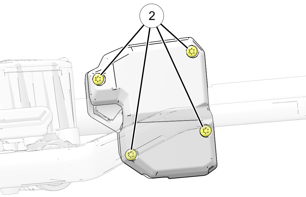
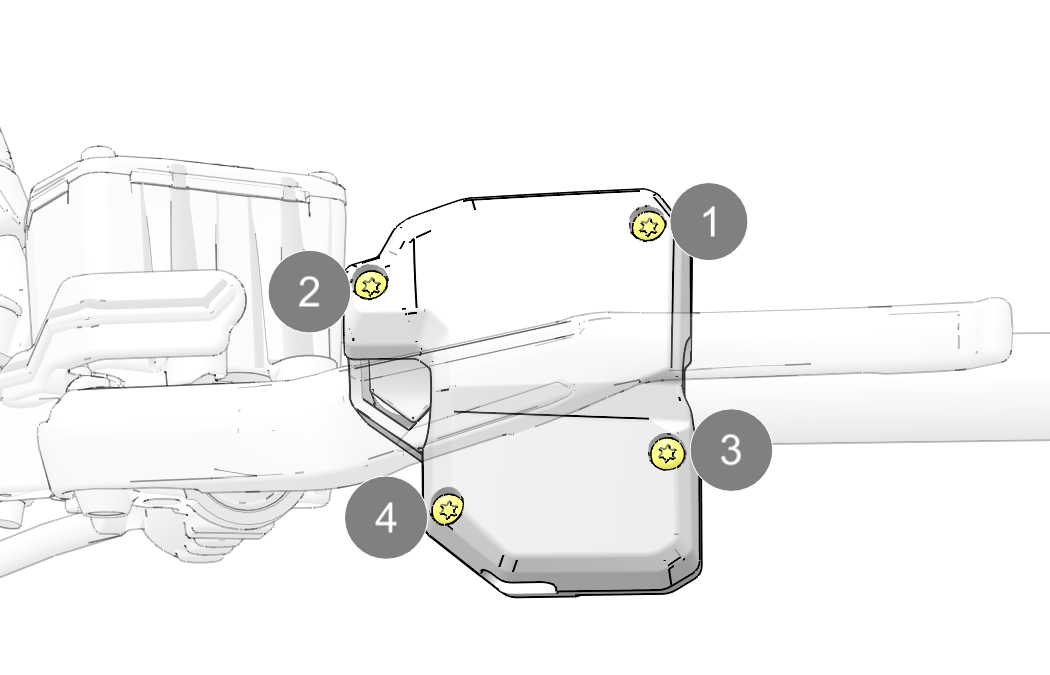
Moving the left hand control without loosening the four
mounting screws will cause the housing locating pins to cut grooves
into the handlebar. When
this occurs, the left hand control may not clamp tightly to the handlebar.
If the left hand control was inadvertently moved without
loosening the screws and is loose, move the control block slightly
to the left of right
on the handlebars to re-locate the pins.
|
|
Use care when moving brake master cylinder. Do not damage
the brake light signal wire. |
| NOTICE |
|
If applicable, hand guards or mountain bar may need to
be loosened or removed to access and move the brake master cylinder. |
| TORQUE | |
|
Left Hand Control Screws: 20 in-lbs (2.3 Nm) Do not over-torque. |
| TORQUE | |
|
Brake Master Cylinder Clamp: 60 - 80 in-lbs (6.8 - 9 Nm) Torque screw farthest from the reservoir and then the screw next to reservoir. Do not over-torque. |
© Copyright Polaris Industries Inc. All rights reserved.