
Content Source: 2020 800 Titan Adventure Owner’s Manual (9929779 Rev 02) > Features Chapter
| IMPORTANT |
|
The Owner's Manual for this vehicle contains warnings, instructions and other information you must read and fully understand before safely riding or performing maintenance on this vehicle.Always follow the warnings and instructions in Owner's Manual. Click the CONTENTS link above for the Table Of Contents, or download a full PDF of the Owner Manual in the Owner Support area of Polaris.com |
| NOTE |
|
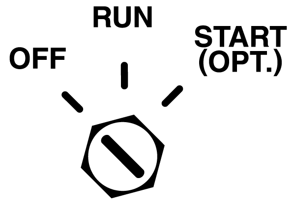
If the key remains in the RUN position after using the
engine stop switch to stop the engine, the PIDD (POLARIS Interactive
Digital Display) remains
active. The PIDD screen will turn off after several minutes of inactivity,
but if a battery is installed,
the PIDD will continue
to draw a small amount of current from the battery until the key is
turned off. This feature is useful
for accessing the PIDD
without starting the engine, but turn the key off when the PIDD is
not in use.
The PIDD is not dependent on a battery while the engine
is running, but a battery (if installed) supplies a constant power
source when the engine
is turned off or when the engine is transitioning between forward
and reverse operation. If a battery
is not installed, the
PIDD reboots when the engine is started and when electronic reverse
(PERC) is used.
|
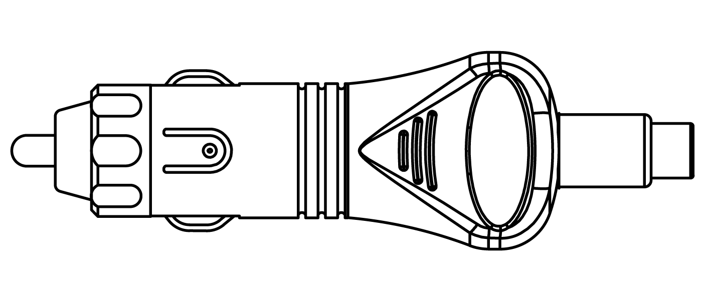
The RCA adapter can be used if your model is equipped with the 12-volt DC power receptacle. Plug the adapter into the receptacle to convert it to a 12-volt RCA power outlet.
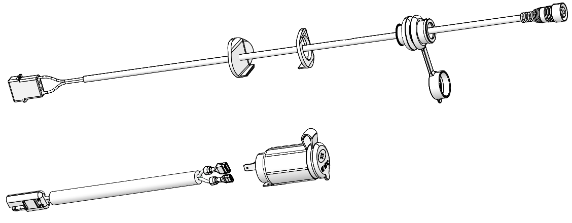
The RCA power plug (with cover) mounts to the handlebar cover and is plugged into the main vehicle wire harness. Installation instructions are provided with the accessory. This power point is powered by the load shed relay and is not fuse protected. POLARIS recommends using this power point for electric helmet shields.
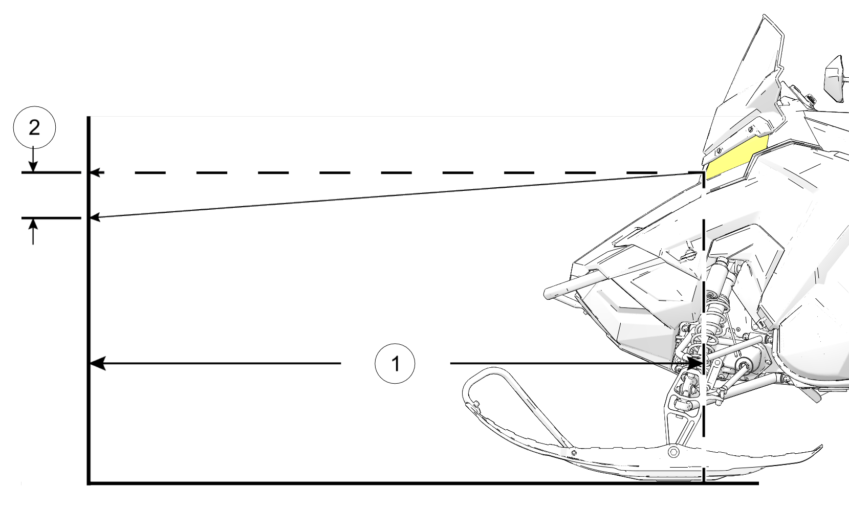
| NOTE |
| The image below is for reference only. Your model may differ slightly. |
| NOTE |
|
The spare belt and spark plugs are not included with
the vehicle from the factory. |
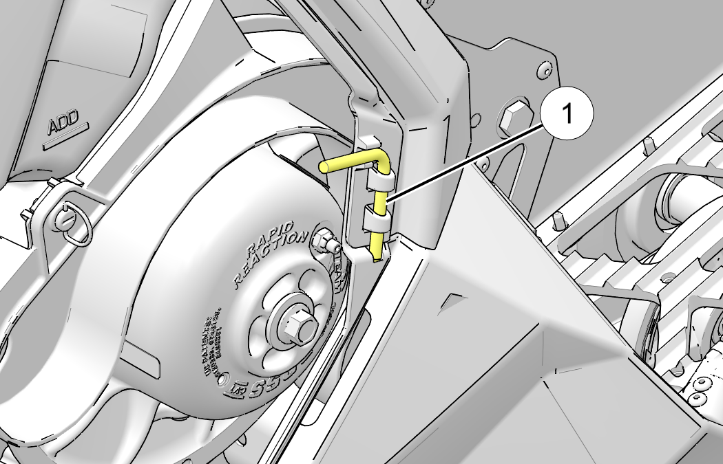
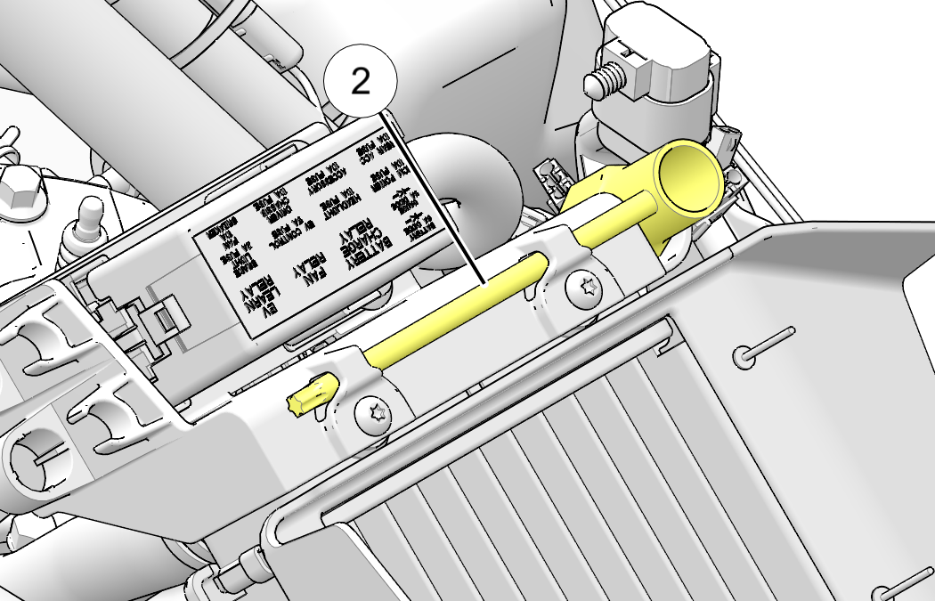
The L-wrench ![]() is used to open and close the driven clutch
when working with the drive belt. The L-wrench, when properly engaged
in the
bracket, secures the fender to the console. To retrieve
the L-wrench, rotate it counterclockwise and slide it upward from
the bracket. When it’s not in use, return the L-wrench
to the bracket and rotate it clockwise.
is used to open and close the driven clutch
when working with the drive belt. The L-wrench, when properly engaged
in the
bracket, secures the fender to the console. To retrieve
the L-wrench, rotate it counterclockwise and slide it upward from
the bracket. When it’s not in use, return the L-wrench
to the bracket and rotate it clockwise.
The spark
plug wrench ![]() . To retrieve the spark plug wrench, rotate
it counterclockwise and slide it outward from the bracket. When it’s
not in use,
return the spark plug wrench to the bracket and
rotate it clockwise.
. To retrieve the spark plug wrench, rotate
it counterclockwise and slide it outward from the bracket. When it’s
not in use,
return the spark plug wrench to the bracket and
rotate it clockwise.
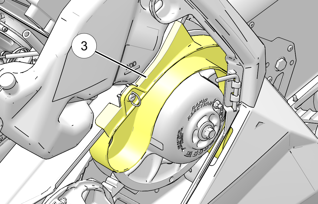
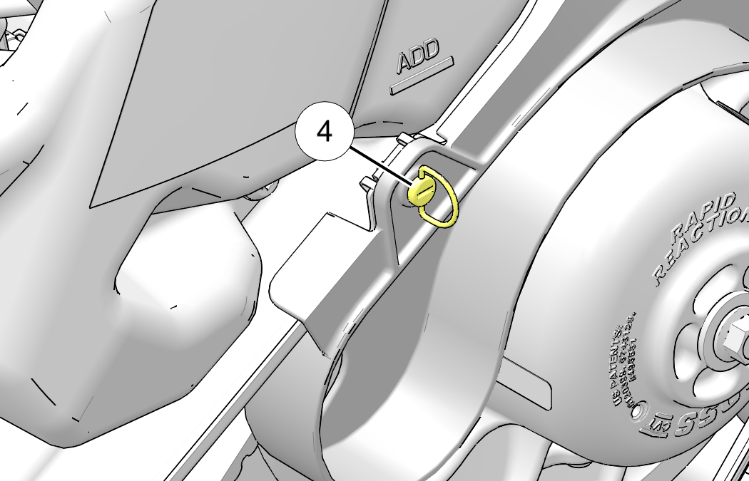
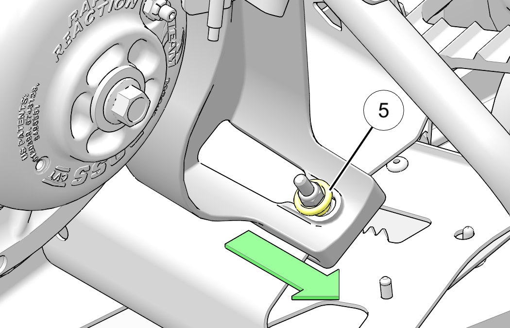
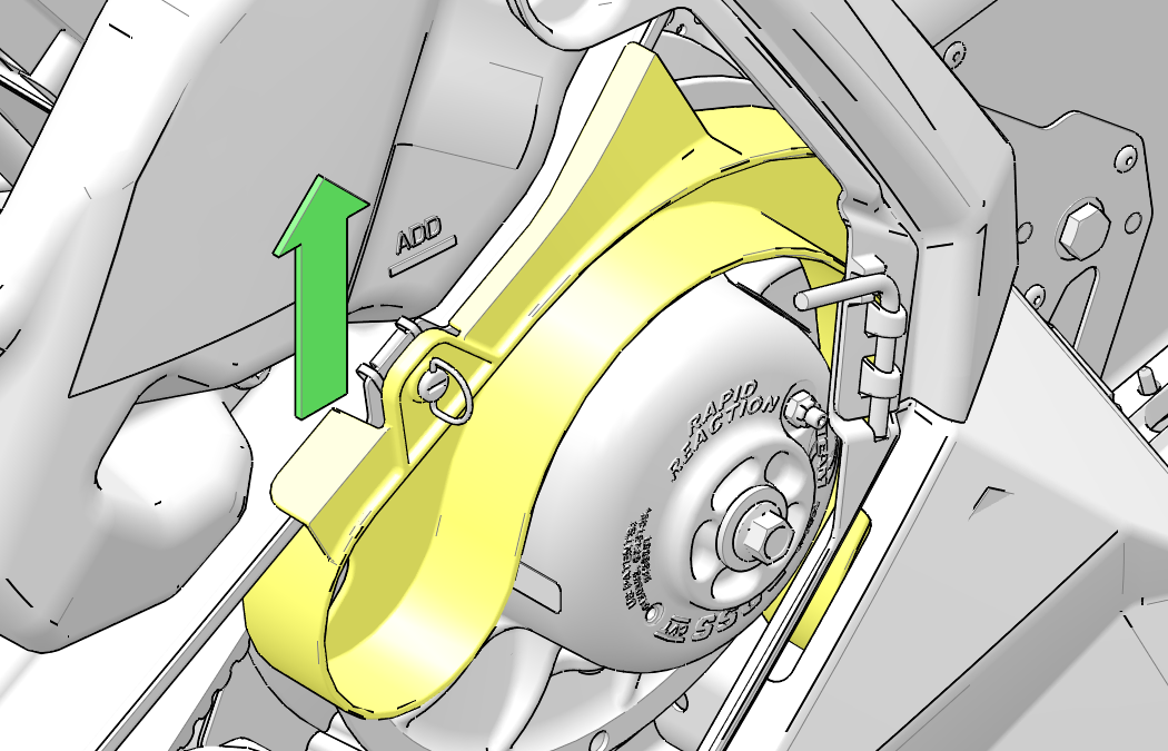
The spare
belt holder ![]() attached to the clutch guard. Use the following
procedure to remove the spare belt holder from the snowmobile.
attached to the clutch guard. Use the following
procedure to remove the spare belt holder from the snowmobile.
| NOTE |
|
Fender has been removed form image clarity. |
| NOTICE |
| Do not install accessory bogie wheels on the inside of the rail beams if your model is equipped with a remote reservoir rear track shock or damage will occur. The rail scratchers must be removed as they interfere with the accessory bogie wheels. |
|
DETONATION PROTECTION MODES |
|
|---|---|
|
Check Engine LED/Gauge Display |
Protection Mode |
|
800 Models |
|
|
LED illuminated / “DETONATION” displayed |
Slight drop in engine RPM/power |
|
LED flashing / “DETONATION” displayed |
Exhaust valves close to reduce engine RPM/power. Restart engine to reset. |
| NOTE |
| The PIDD alert indicates which cylinder is experiencing detonation |
| NOTE |
| If equipped with an PIDD, the gauge will remain on because the key is in the ON position. |
| Gear Position | Speed Limit |
|---|---|
| Neutral | N/A |
| Reverse — Override button off (button not pressed) | 10 mph (16 kph) |
| Reverse — Override button on (button pressed) | 20 mph (32 kph) |
| Low | 45 mph (72 kph) |
| Low/high — Speed sensor signal lost | Exhaust valves set to closed position |
| Reverse — Speed sensor signal lost |
© Copyright Polaris Industries Inc. All rights reserved.