Content Source: 2020 Scout/Scout Sixty Owner’s Manual (9929430 R03) > Maintenance Chapter

IMPORTANT

The Owner's Manual for this vehicle contains warnings, instructions and other information you must read and fully understand before safely riding or performing maintenance on this vehicle.Always follow the warnings and instructions in Owner's Manual.

Click the CONTENTS link above for the Table Of Contents, or download a full PDF of the Owner Manual in the Owner Support area of Polaris.com

Drive Belt Tension / Alignment

Lifting the Motorcycle

WARNING
Failure to properly lift and stabilize motorcycle may allow it to tip or fall, resulting in severe personal injury or death.
  1. Position motorcycle platform jack beneath engine case, avoiding oil drain plug, and lift motorcycle so front wheel is off ground. Stabilize motorcycle in upright position with tie-down straps (or equivalent). Motorcycle MUST be stable prior to performing belt procedures.
    IMPORTANT
    Automotive floor jack does not provide adequate stability and is NOT RECOMMENDED!
    Image

Drive Belt Tension Check

Special Tool: Belt Tension Gauge PV-43532
IMPORTANT
Perform this procedure to achieve proper belt tension and alignment. Belt tension should be set before performing alignment procedure.
WARNING
A drive belt that is not properly tensioned can cause drive line noise and damage the drive belt, causing possible belt failure and loss of control of the motorcycle.
  1. Inspect drive belt for damage and wear.
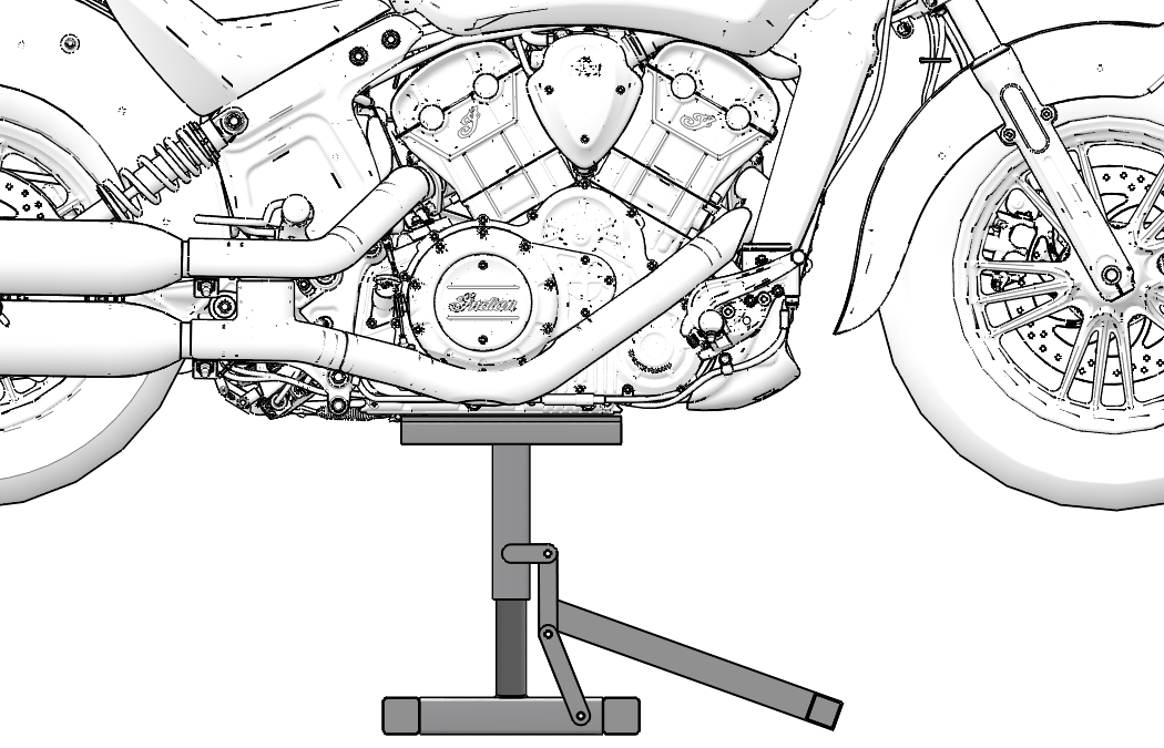
  2. Ensure rear wheel is elevated before checking tension or adjusting.
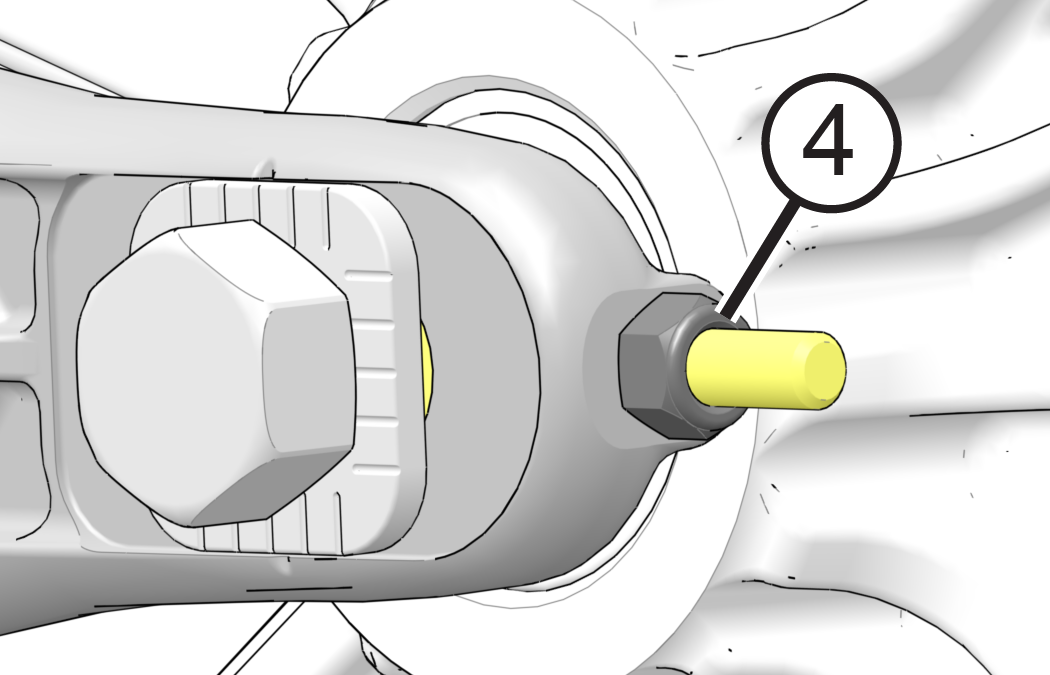
  3. Use tire valve stem as a reference and perform following steps:
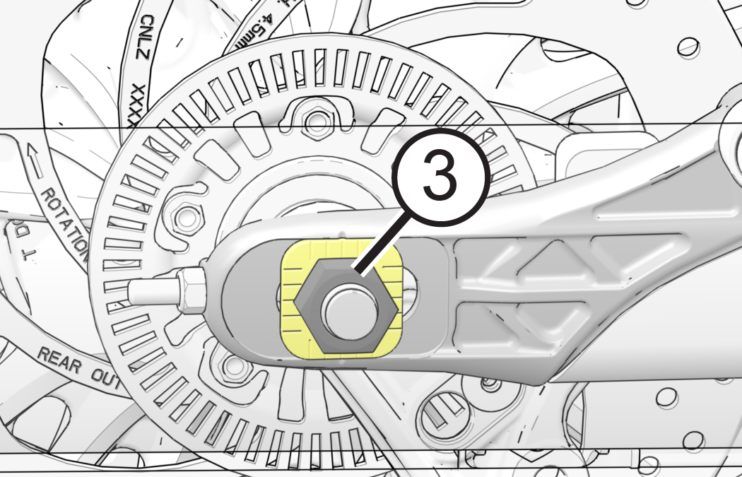
    1. Check/record belt deflection at 4 different points, 90° apart. Rotate wheel in a COUNTER-CLOCKWISE rotation as viewed from belt side of motorcycle.
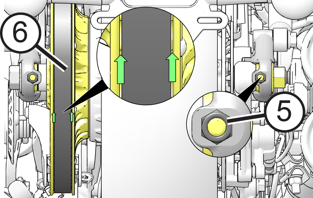
    2. Place a mark on rear wheel at tightest point (least deflection) to use as a reference.
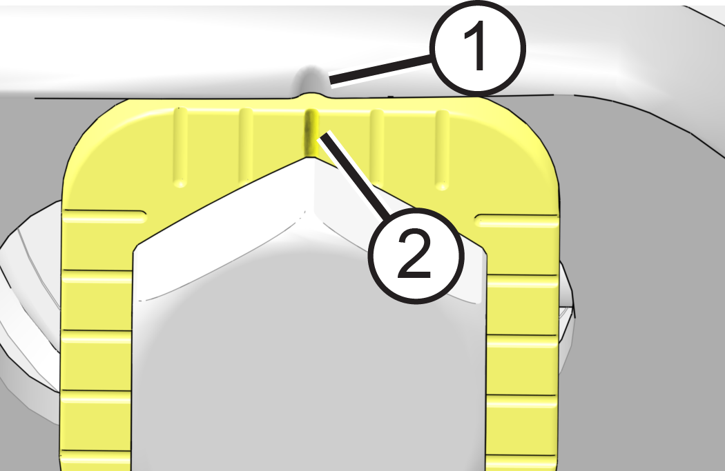
    3. Continue to rotate wheel in normal drive direction (COUNTER-CLOCKWISE) 1–2 revolutions until your reference mark (tightest point) is lined up with tension setting window in lower belt guard.
      Image
    4. Adjust belt deflection with wheel in this position.
  4. Place tape measure or ruler next to drive belt.
  5. Slide O-ring on belt tension gauge to 10 lb. mark.
  6. Place belt tension gauge (Special tool PV-43532) squarely against belt at center and keep it at a 90° angle to the belt surface.
  7. Push up on gauge until O-ring just touches tool body and compare to specification.
    MEASUREMENT

    Drive Belt Deflection @ 10 lbs force:

    12 mm (15/32 in)

  8. If belt deflects more than specified distance with 10 lbs. of force, proceed to Drive Belt Adjustment section and tighten belt. If belt deflection is less than specified, proceed to Drive Belt Adjustment section and loosen belt. If belt deflection is correct, lower motorcycle.

Drive Belt Tension Adjustment and Alignment

IMPORTANT
Perform this procedure to achieve proper belt tension and alignment. Belt tension should be set before performing alignment procedure.
Belt Tension
WARNING
A rear axle not in alignment can cause drive line noise and damage the drive belt, causing possible belt failure and loss of control of motorcycle.
  1. Make note of adjuster locations and .
    Image
  2. On right side of motorcycle, loosen axle nut and retighten to Adjustment Specification.
    TORQUE
    Adjustment Specification: 15 ft. lbs. (20 Nm)
    Image
  3. Turn LEFT SIDE adjuster nut to achieve proper belt tension.
    Image
  4. When belt tension is correct continue to next section and adjust final belt alignment.
Belt Alignment
WARNING
Drive belt misalignment can cause drive line noise and damage drive belt, causing possible belt failure and loss of control of motorcycle.
NOTE
To minimize change in belt tension, use RIGHT SIDE adjuster only to make final adjustments to belt alignment. Be sure to keep axle seated forward against axle adjusters during this procedure.
  1. Rotate wheel BACKWARD. Tighten RIGHT SIDE adjuster nut until drive belt comes off inside sprocket flange during backward wheel rotation and is centered in driven pulley as shown with arrows..
    IMPORTANT
    Belt should track to center of sprocket tooth surface when properly aligned. Sprocket teeth should be visible on both sides of drive belt.
    Image
  2. Rotate wheel FORWARD and verify sprocket teeth are still visible on both side of drive belt.
  3. If necessary, loosen axle nut and RIGHT SIDE adjuster until belt moves off left flange and begins to track down center of driven sprocket flange during forward wheel rotation.
    NOTE
    It may be necessary to loosen axle nut and tap left end of axle to ensure it moves forward when adjuster is loosened. Axle nut must be retightened to Adjustment Specification (15 ft. lbs. (20 Nm)) before proceeding.
  4. Rear wheel alignment is satisfactory when drive belt remains centered on driven sprocket during forward and backward wheel rotation. Sprocket teeth should be visible from both sides of drive belts.
  5. Verify drive belt tension is still within specification. (See Check Drive Belt Tension section)
  6. Tighten rear axle nut to Final Specification.
    TORQUE
    Final Specification: 65 ft. lbs. (88 Nm)
  7. Pump rear brake pedal several times to reset brake pad distance.
  8. Verify wheel rotates smoothly and freely without drag when brake pedal is released.
  9. Lower motorcycle.

© Copyright Polaris Industries Inc. All rights reserved.