
Content Source: MY19 GEM e2 / e4 / e6 / eL XD (9929175 R02) > Maintenance Chapter
| IMPORTANT |
|
The Owner's Manual for this vehicle contains warnings, instructions and other information you must read and fully understand before safely riding or performing maintenance on this vehicle.Always follow the warnings and instructions in Owner's Manual. Click the CONTENTS link above for the Table Of Contents, or download a full PDF of the Owner Manual in the Owner Support area of Polaris.com |
| Operating your vehicle with worn tires, improperly inflated tires, non-standard tires or improperly installed tires will affect vehicle handling and could cause an accident resulting in serious injury or death. Always follow all tire maintenance procedures as outlined in this manual and on the labels on the vehicle. Always use original equipment size and type when replacing tires. |
| Improper tire pressure can cause loss of control resulting in severe injury or death. |
| NOTICE |
| After inspecting or adjusting the tire pressure, always reinstall the valve stem cap (if equipped). This will prevent moisture and dirt from entering the valve stem, which could cause damage. |
Any accelerated wear
of tires may be an indicator of improper alignment or poor driving
habits. Your authorized GEM dealer
can assist.
Rotate
wheels every 5,000 miles, or more frequently if needed.
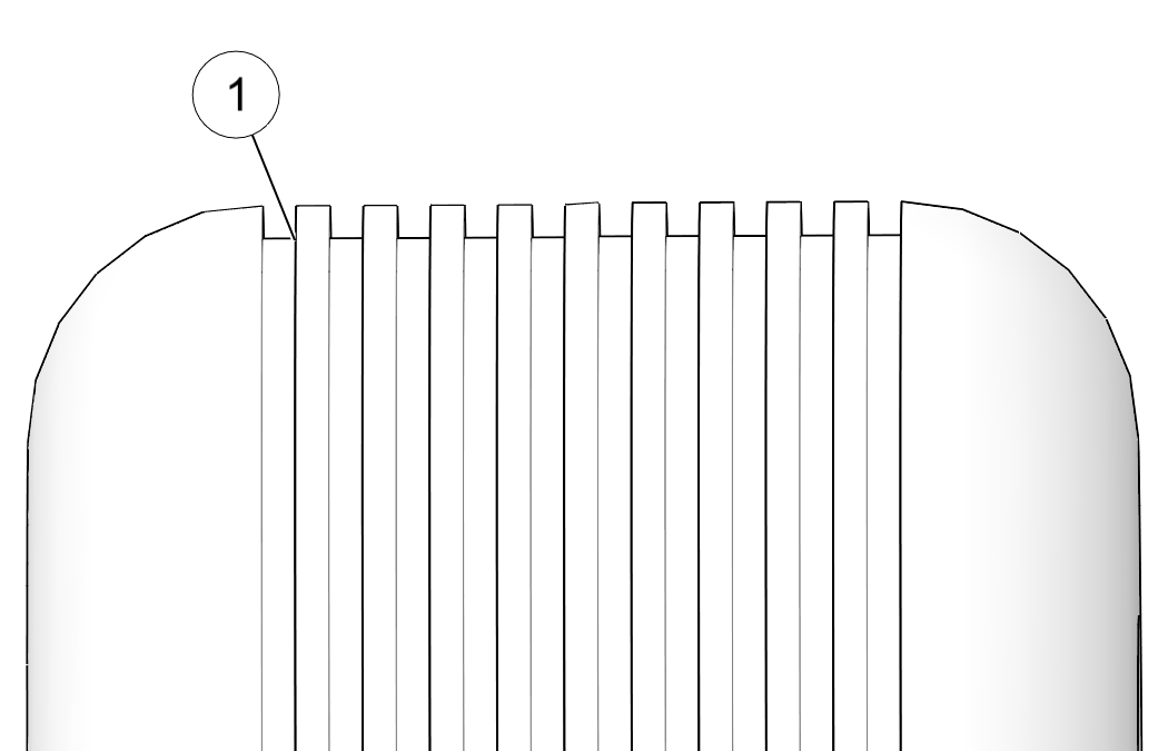
Always replace tires when tread depth is worn to
1/8” (3 mm) or less. ![]()
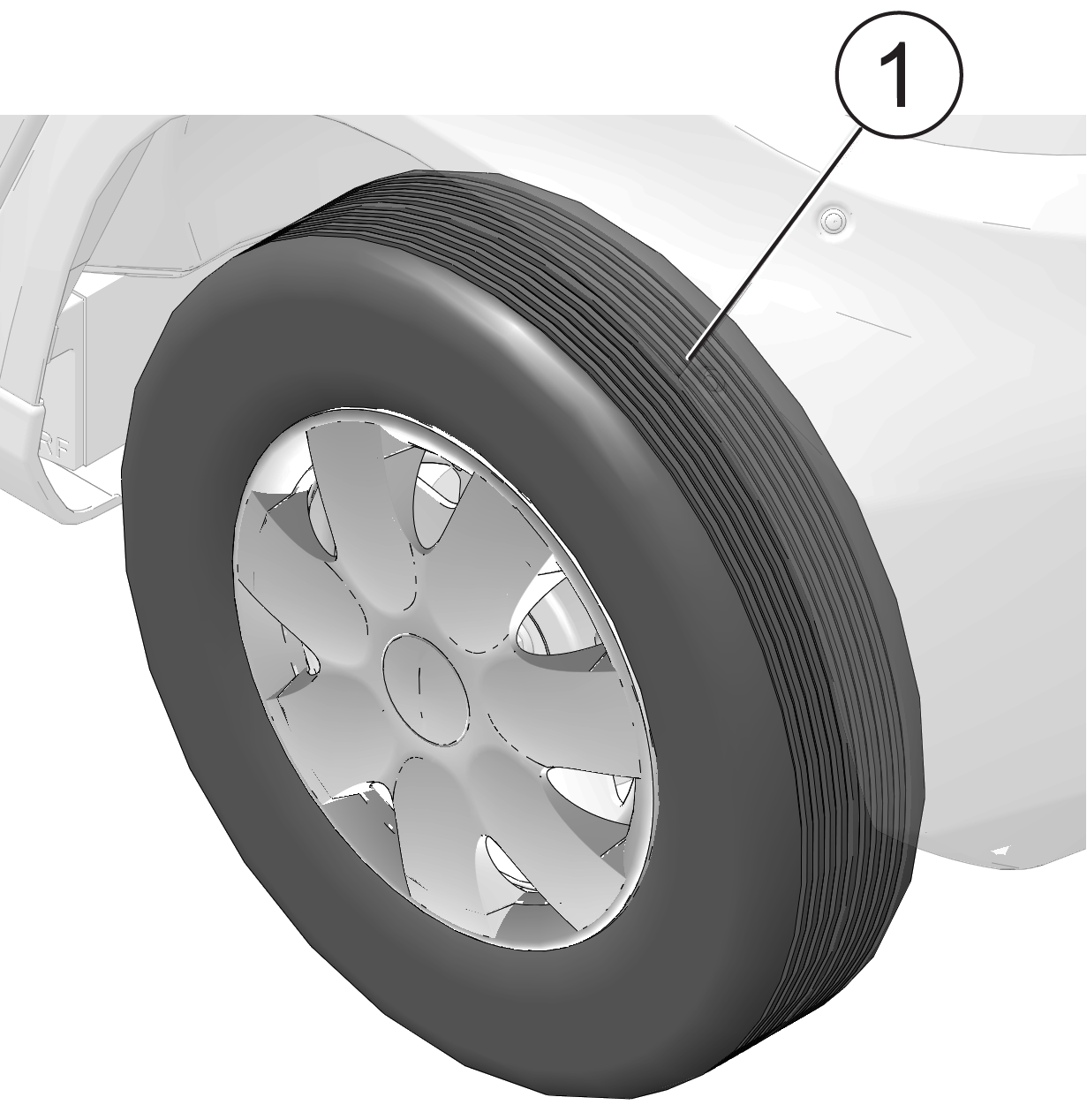
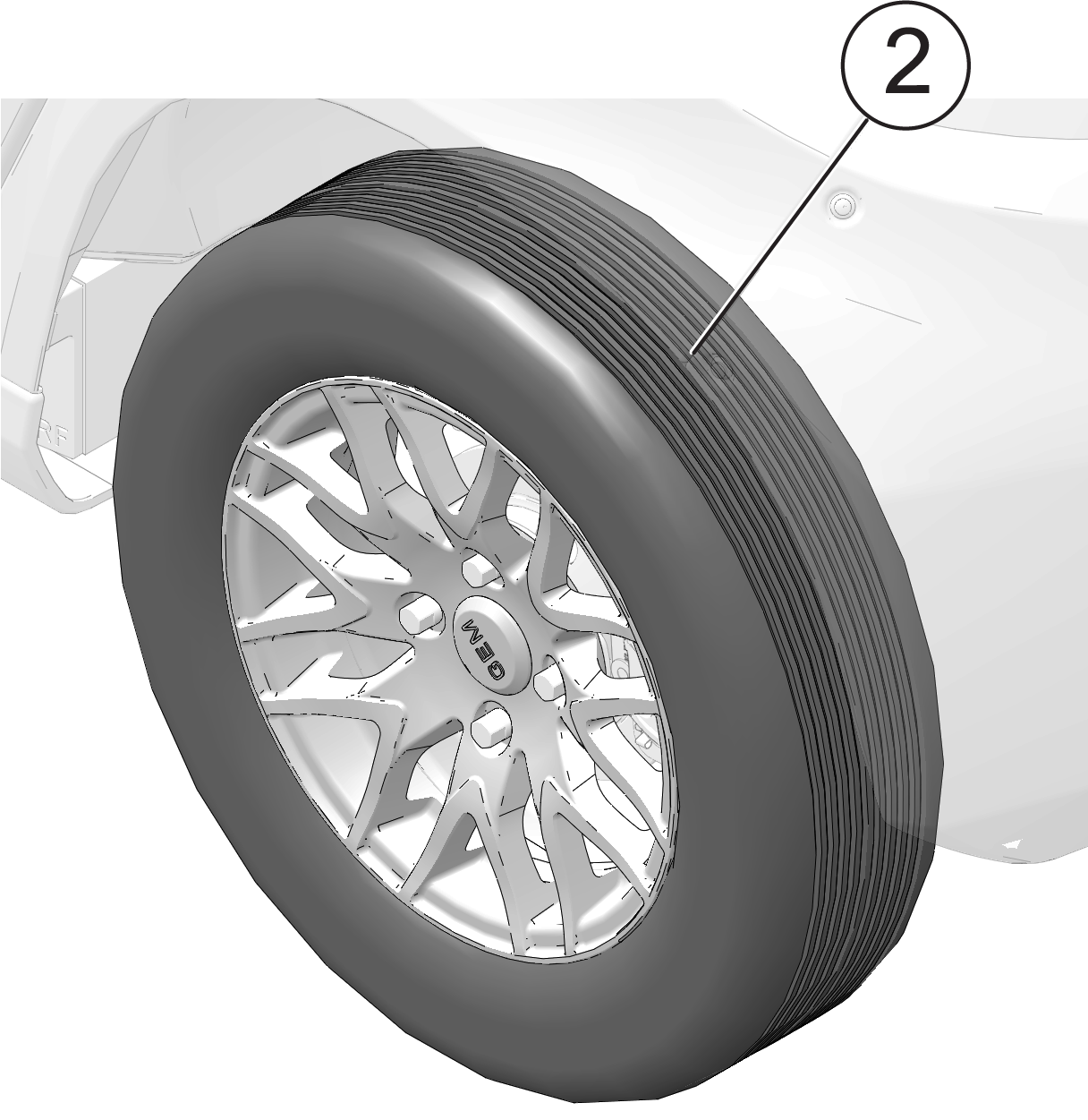
| A falling vehicle can cause serious injury or death. Never place any part of your body under an elevated vehicle. If you need access to the bottom of the vehicle, use automotive jack stands to support the vehicle on a firm, level surface. Your authorized GEM dealer can assist. |
| NOTICE |
| Jacking at any location other than the recommended jacking points may cause significant damage to the vehicle frame and body. |
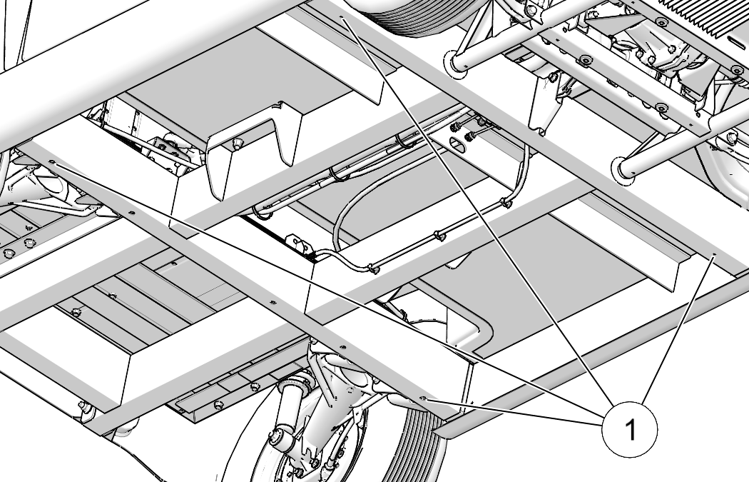
| Improperly installed wheels can adversely affect tire wear and vehicle handling, which can result in serious injury or death. Always ensure that all nuts are torqued to specification. Do not service axle nuts that have a cotter pin installed. Your authorized dealer can provide service. |
| TIP |
| To ensure that the washers fully seat in the wheel taper, use other hand to position and center wheel, if necessary. |
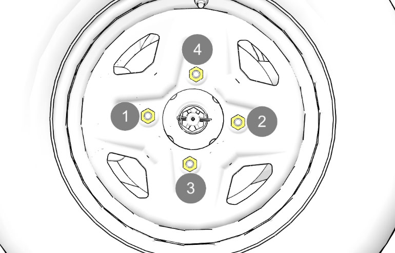
| IMPORTANT |
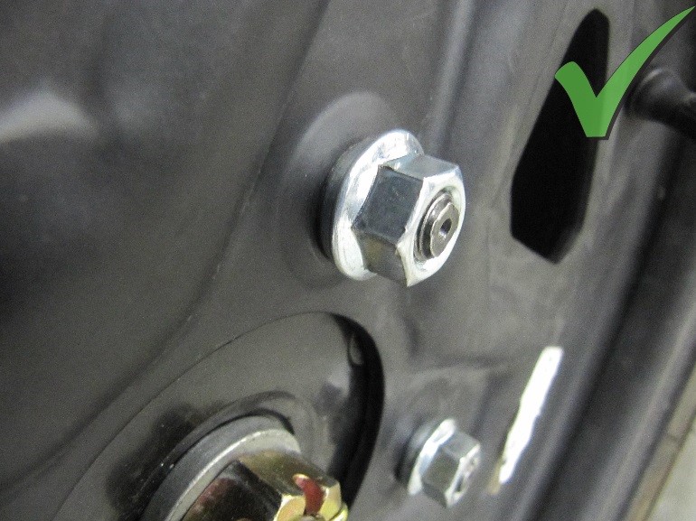
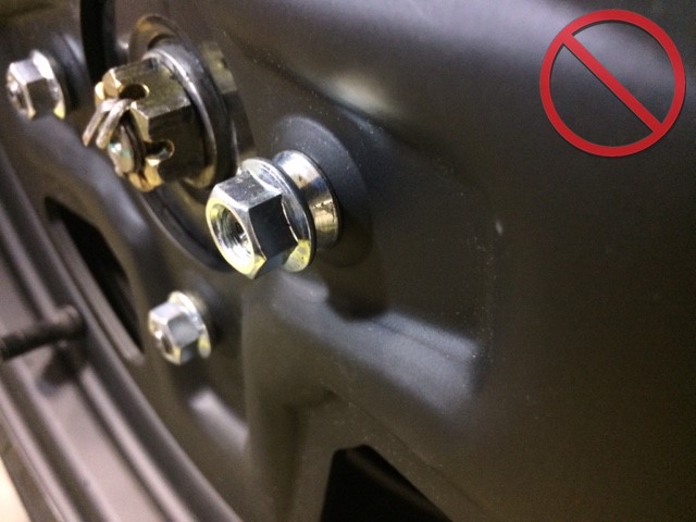
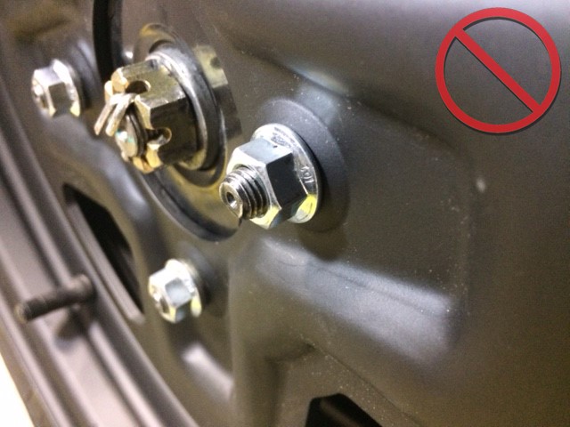
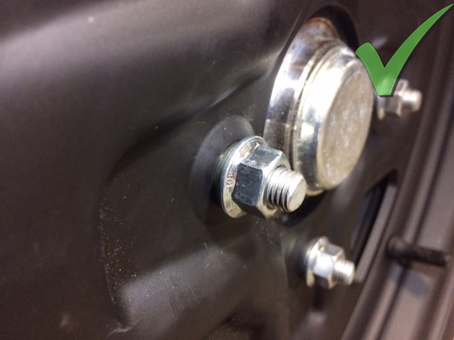
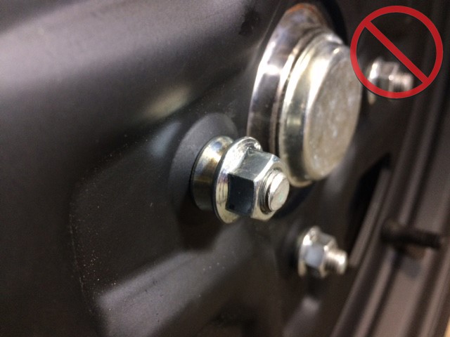
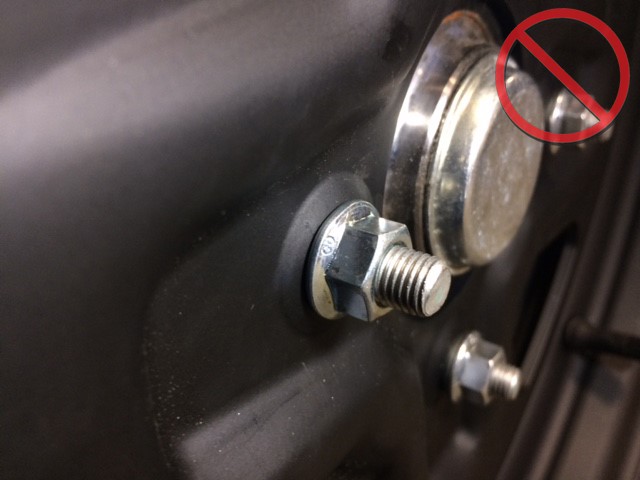
| A secondary dealer representative must verify that all sixteen flange nuts are raised off of the rim and do not make contact with the rim. Then mark each lug nut with a paint pen. |
© Copyright Polaris Industries Inc. All rights reserved.