Content Source: 2019 GEM e246 INTL Owner’s Manual (9929174 R03) > Features and Controls Chapter
| IMPORTANT |
|
The Owner's Manual for this vehicle contains warnings, instructions and other information you must read and fully understand before safely riding or performing maintenance on this vehicle.Always follow the warnings and instructions in Owner's Manual. Click the CONTENTS link above for the Table Of Contents, or download a full PDF of the Owner Manual in the Owner Support area of Polaris.com |
| NOTICE |
| Liquids can damage electrical components and the circuit board. Handle liquids with care. Do not spray water directly into the upper or lower console. |
Electrical wiring,
circuit boards and components are located under and behind the upper
and lower console ![]() .
.
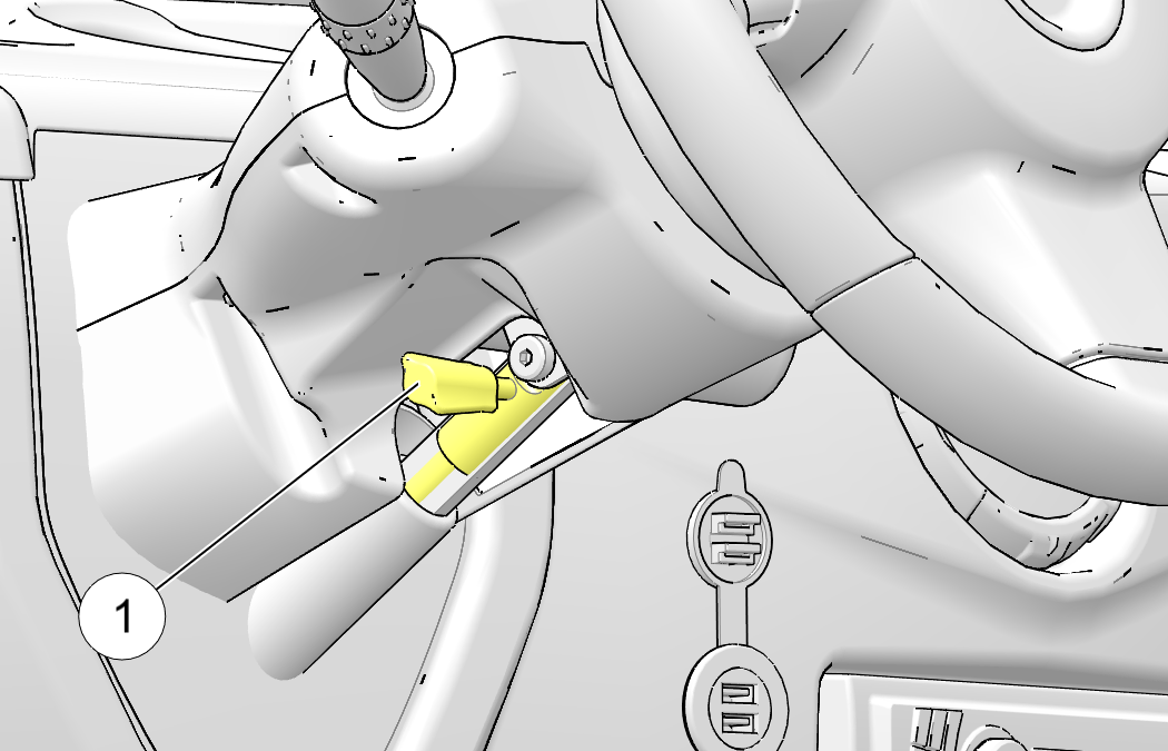
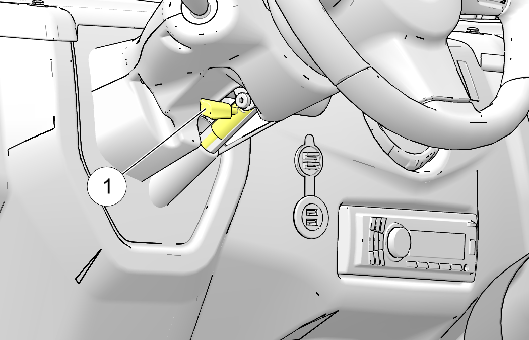
If equipped, the steering
wheel can be tilted upward or downward for rider preference.
Pull and hold the adjustment lever ![]() upward while moving the steering wheel upward
or downward. Release the lever when the steering wheel is at the desired
position.
upward while moving the steering wheel upward
or downward. Release the lever when the steering wheel is at the desired
position.
| NOTICE |
| The steering column automatically locks when the ignition key is
removed.
The key can be removed from the switch when it is in
the OFF position. |
| Never turn the key to the OFF position while the vehicle is in motion. This could lead to loss of speed control and loss of vehicle control, which could result in serious injury or death. |
| NOTICE |
| The key must be in the ON position to activate the turn signals. |
Check turn signal
lamps before each ride. When driving, activate a turn signal before
turning to alert others of your intentions.
Move the lever upward ![]() to
signal a right turn. Move the lever downward
to
signal a right turn. Move the lever downward ![]() to signal a left turn. The corresponding
turn signal lamps on the front and rear of the vehicle will flash.
The corresponding
turn indicator in the LCD display will also flash.
to signal a left turn. The corresponding
turn signal lamps on the front and rear of the vehicle will flash.
The corresponding
turn indicator in the LCD display will also flash.
Press the tip of
the left control lever ![]() inward to sound the horn.
inward to sound the horn.
| caution |
| Changing the direction switch position while driving could result in an automatic increase or decrease in speed without a change to accelerator pedal pressure. |
| NOTICE |
| Always bring the vehicle to a complete stop before changing the position of the direction switch. |
| MODE | PROCEDURE |
|---|---|
|
Forward |
Move the lever fully upward to operate in forward mode. The forward mode allows operation of the vehicle at speeds of 0-25 MPH (0-40 km/h). |
|
Neutral |
Move the lever to the center position to prevent the vehicle from moving if the accelerator is pressed. |
|
Reverse |
Move the lever fully downward to operate in reverse mode. A reverse warning alert will automatically sound when the key is on and reverse mode is selected. Vehicle speed is limited when operating in reverse. See Driving in Reverse for safe reverse operation procedures. |
| caution |
| A worn or damaged wiper blade could impair operator vision and result in an accident. A worn wiper blade could also damage windshield glass. Always replace worn or damaged wiper blades promptly. |
High water pressure may damage components. Wash the vehicle by hand or with a garden hose using mild soap. Certain products, including insect repellents and chemicals, will damage the speedometer lens and other plastic surfaces. Do not use alcohol to clean the instrument cluster. Do not allow insect sprays to contact the lens.
|
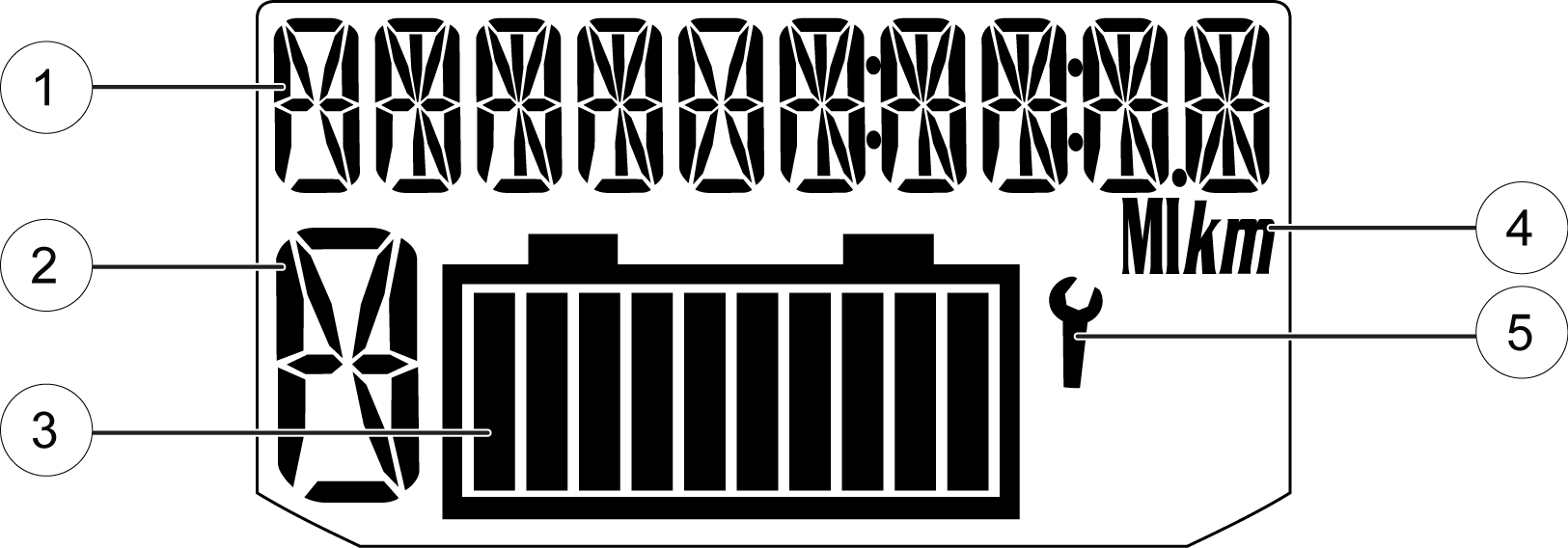
Lamp |
Indicates |
Condition |
|---|---|---|
|
|
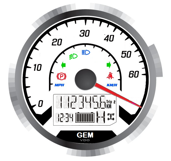
Vehicle Speed |
When standard mode is selected, speed displays in miles per hour. |
|
|
When metric mode is selected, speed displays in kilometers per hour. |
|
|
|
Brake Indicator |
The brake indicator illuminates when the park brake is engaged or when a brake system failure has occurred. If the brake warning illuminates, check the following items before operating the vehicle |
|
|
Direction Indicators |
A direction indicator flashes when a turn signal is active. |
|
|
Low Beam |
This lamp illuminates when the headlamp switch is set to low beam. |
|
|
High Beam |
This lamp illuminates when the headlamp switch is set to high beam. |
|
|
Seat Belt |
When the key is turned on, the seat belt indicator lamp will illuminate if the driver’s seat belt is not fastened. The lamp is a reminder to the operator to ensure all riders are wearing seat belts before operating. |
|
Brake System Item |
Solution |
|---|---|
|
Park brake |
Release the park brake. |
|
Brake fluid level |
If low, add brake fluid. See Brake Fluid. |
|
Brake system |
Check hoses for cracks, scuffs and worn spots. If you discover signs of wear or damage, do not operate the vehicle. Your authorized GEM dealer can provide service. |
| Worn or damaged brake hoses can cause brake failure. Always have worn or damaged brake hoses replaced promptly. |
|
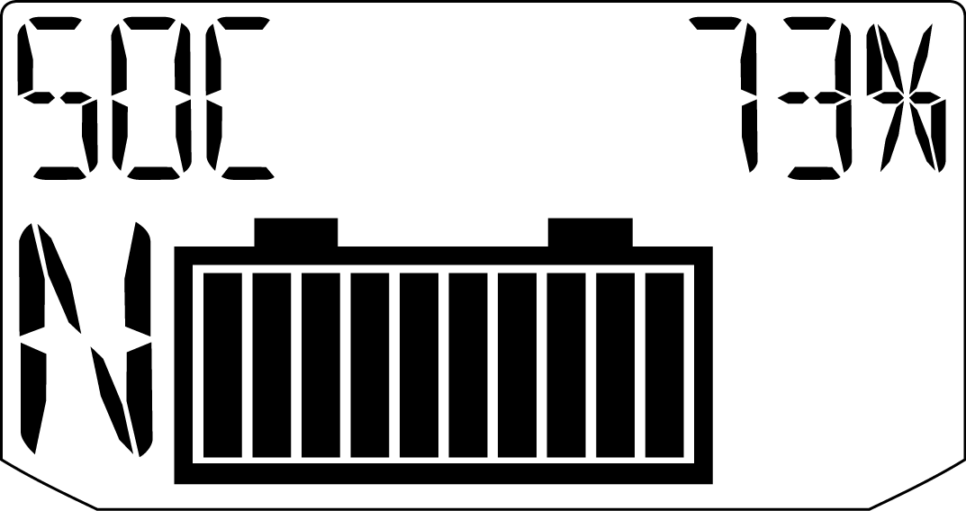
State of Charge Indicator |
|
|---|---|
|
Bars |
% Of Charge |
|
1 |
Less Than 10 |
|
2 |
10-20 |
|
3 |
20-30 |
|
4 |
30-40 |
|
5 |
40-50 |
|
6 |
50-60 |
|
7 |
60-70 |
|
8 |
70-80 |
|
9 |
80-90 |
|
10 |
90-100 |
| NOTE |
|
All Polaris/GEM electric vehicles with
lead-acid batteries do not factor battery temperature into state of
charge. If batteries
are stored at
cold temperatures, the amount of available stored energy on a full
charge is reduced. This is most pronounced
at temperatures
below 32°F.
|
| TEMP (° F) | BATTERY CAPACITY (%) |
|---|---|
| 80 | 100 |
| 65 | 90 |
| 50 | 80 |
| 35 | 70 |
| 20 | 60 |
| 5 | 50 |
| -10 | 40 |
| -25 | 30 |
| NOTE |
|
“TEMP” column refers to the ambient
temperature that a vehicle was stored in. |
| NOTE |
|
There are many things that can affect
a vehicle’s range on a charge: driving style, terrain, increased vehicle
payloads, cab
heater usage
and other electrical accessory usage. Even though things like these
can decrease a vehicle’s range, they should
be accounted
for in the state of charge reading.
|
|
Standard Display |
Metric Display |
|
|
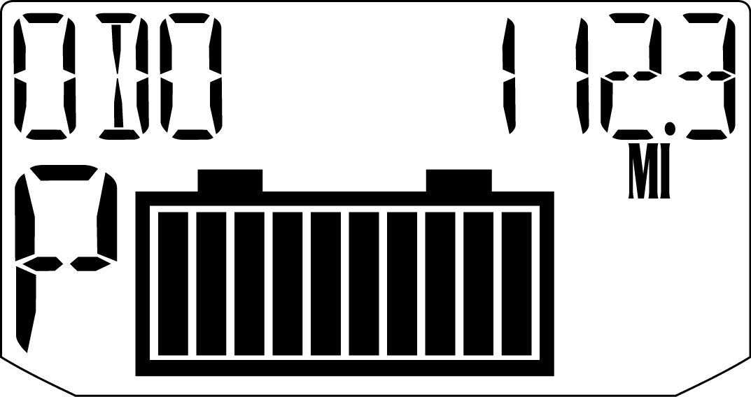
Distance |
Miles |
Kilometers |
|
Temperature |
Fahrenheit |
Celsius |
|
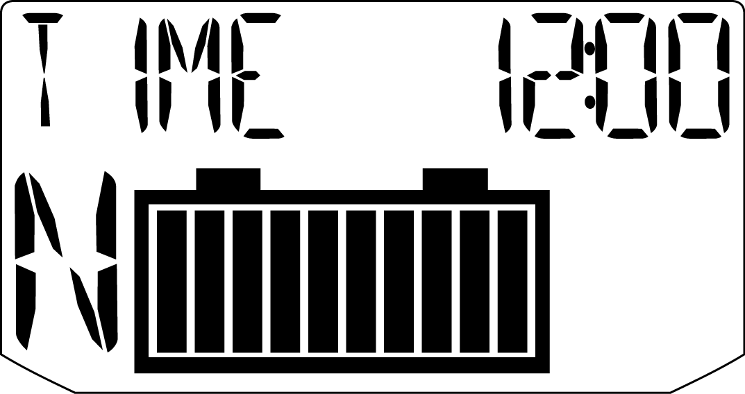
Time |
12-Hour Clock |
24-Hour Clock |
| NOTICE |
| To exit the set-up mode, turn the key off. Wait 5 seconds, then turn the key on. The gauge displays the mode that was displayed prior to setting the units. |
| NOTICE |
| The clock must be reset any time the batteries have been disconnected or fully discharged. |
| TIP |
| The clock must be reset any time the batteries have been disconnected or fully discharged. |
The odometer displays the distance traveled by the vehicle since manufacture.
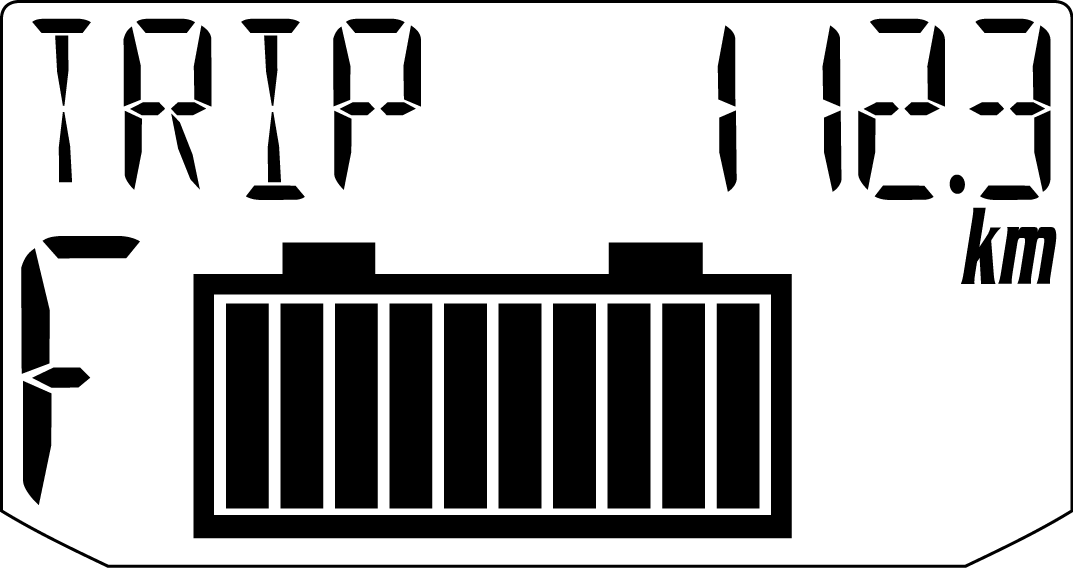
The trip meter displays distance traveled since the last reset of the trip meter. To reset, toggle to the trip meter display. Press and hold the MODE button until the meter resets to zero.
This mode displays the remaining system voltage level in percentage format.
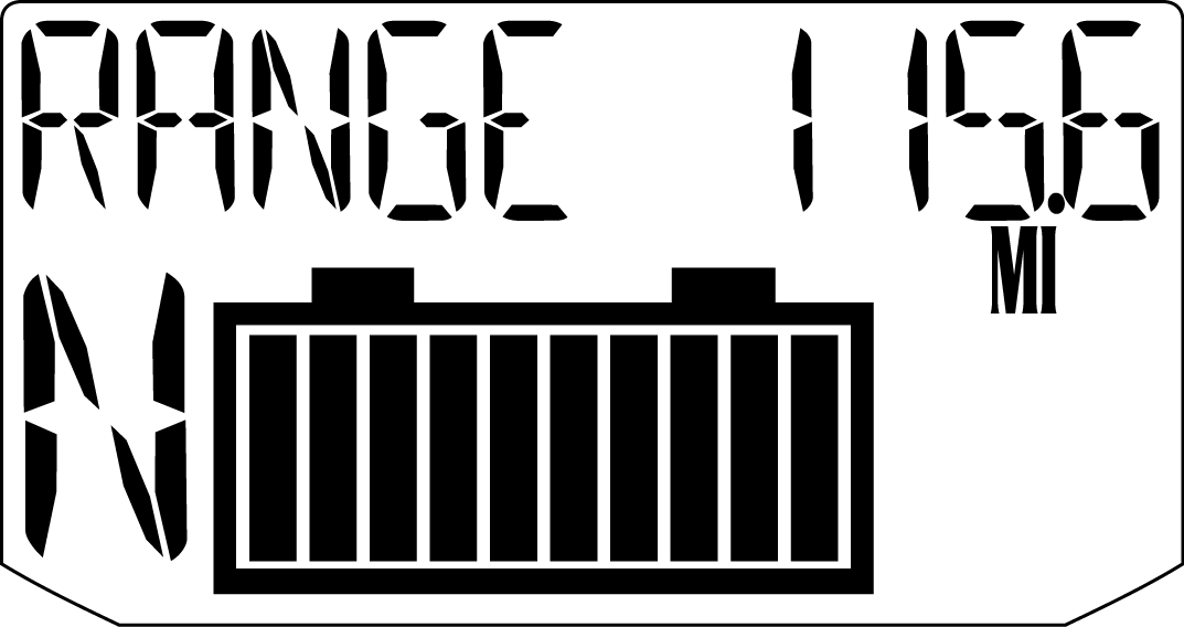
The range meter displays the approximate distance the vehicle could travel on the remaining battery voltage level.
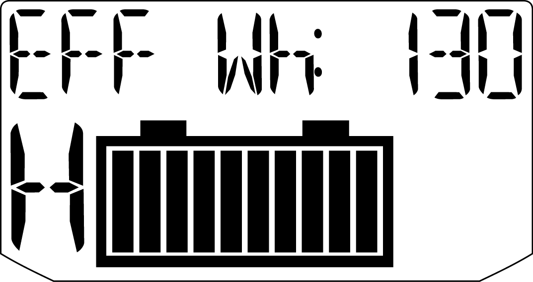
This mode displays the rate at which electrical power (Wh) is consumed per mile or per kilometer. A higher number indicates less desirable efficiency. A lower number indicates better efficiency.
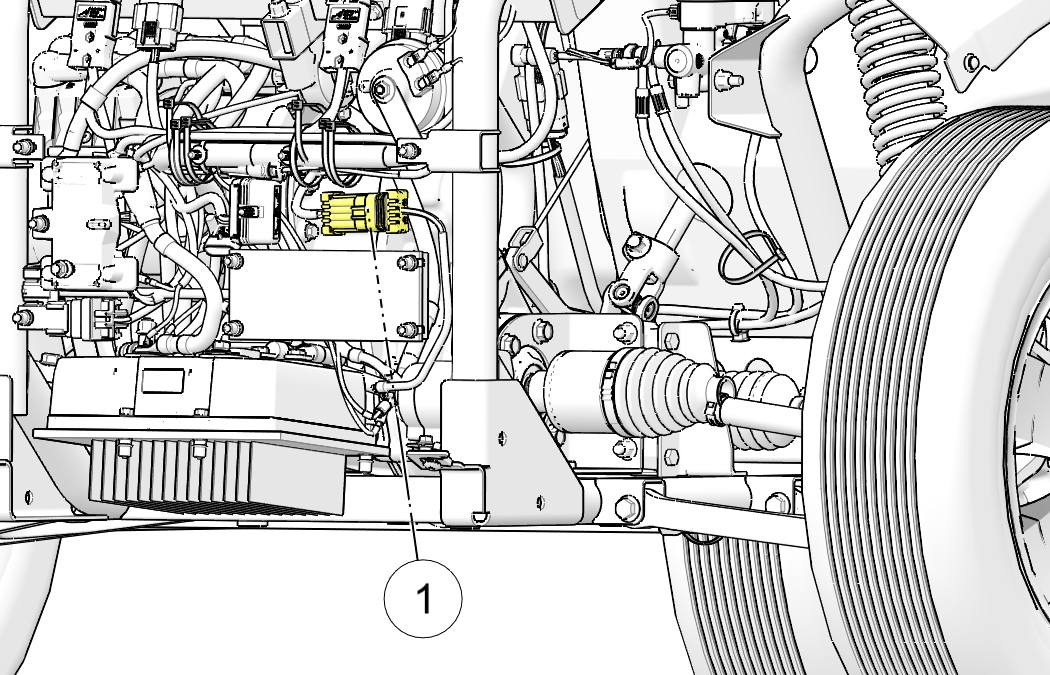
When the main power connector is unplugged, the battery pack is disconnected from all electrical components, with the exception of the contactor. After servicing the vehicle, the main power connector should be the last connection to be made.
| NOTICE |
| Damage to electrical connections and components will occur if they are unplugged before the main power connector is disconnected. |
| Before servicing the vehicle’s electrical system, always disconnect the main power connector first, then disconnect any electrical accessory connections, then disconnect the negative cable from the 12-volt battery (if equipped), then disconnect the negative terminal from the main battery pack. |
| Insulate any tools used within the battery area to prevent sparks or battery explosion caused by shorting the battery terminals or wiring. Remove the batteries, or cover the exposed terminals with an insulating material. |
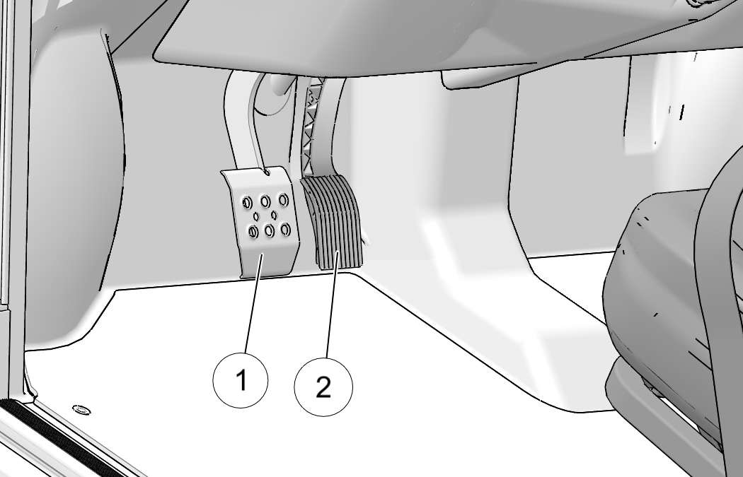
| Constant brake use (riding the brakes) can cause brakes to overheat and fail, which could lead to an accident resulting in serious injury or death. Do not drive with your foot resting or riding on the brake pedal. |
|
A rolling vehicle can cause serious injury. Always set
the park brake when leaving the vehicle unattended.
Remove the key from the ignition to prevent unauthorized
use. |
Always apply the brakes
before setting or releasing the park brake. To release the park brake,
press and hold the park brake
release ![]() and move the lever to the disengaged
position. To set the park brake, pull the park brake lever
and move the lever to the disengaged
position. To set the park brake, pull the park brake lever ![]() slightly upward and toward the center of
the vehicle. If the key is turned off without setting the park brake,
an alert will
sound. Set the park brake to end the alert.
slightly upward and toward the center of
the vehicle. If the key is turned off without setting the park brake,
an alert will
sound. Set the park brake to end the alert.
| NOTICE |
| Be sure the park brake is fully disengaged before driving. Failure to do so can lead to overheating of the rear brakes. |
| NOTE |
| The park brake is adjustable and should be checked periodically as outlined in the Periodic Maintenance Chart beginning on Periodic Maintenance Chart. Your authorized dealer can assist. |
| NOTICE |
| Each vehicle is programmed at the factory for a particular battery type. Switching battery types should be done only by an authorized service technician. Your authorized GEM dealer can provide battery-related service. |
| IMPORTANT |
| Avoid temperature extremes when choosing a storage area. |
| Using a non-recommended extension cord could result in fire, heat damage or charger failure, which could result in serious injury or death. Always use the recommended type of cord to charge the batteries. |
| Charging from a circuit of lesser capacity and/or using a cord from the outlet to the vehicle that is not sufficient in wire gauge could create a fire hazard. |
| Failure to provide adequate ventilation while charging batteries can result in an explosion. Hydrogen gas is emitted during charging and will rise and accumulate at the ceiling. Always ensure a minimum of five (5) air changes per hour in the charging area. Never charge the batteries in an area subject to a flame or spark, including areas containing gas or propane water heaters and furnaces. Do not smoke in the charging area. |
| TIP |
| Do not use a ground fault interrupt (GFI) type cord on a GFCI-protected outlet. |
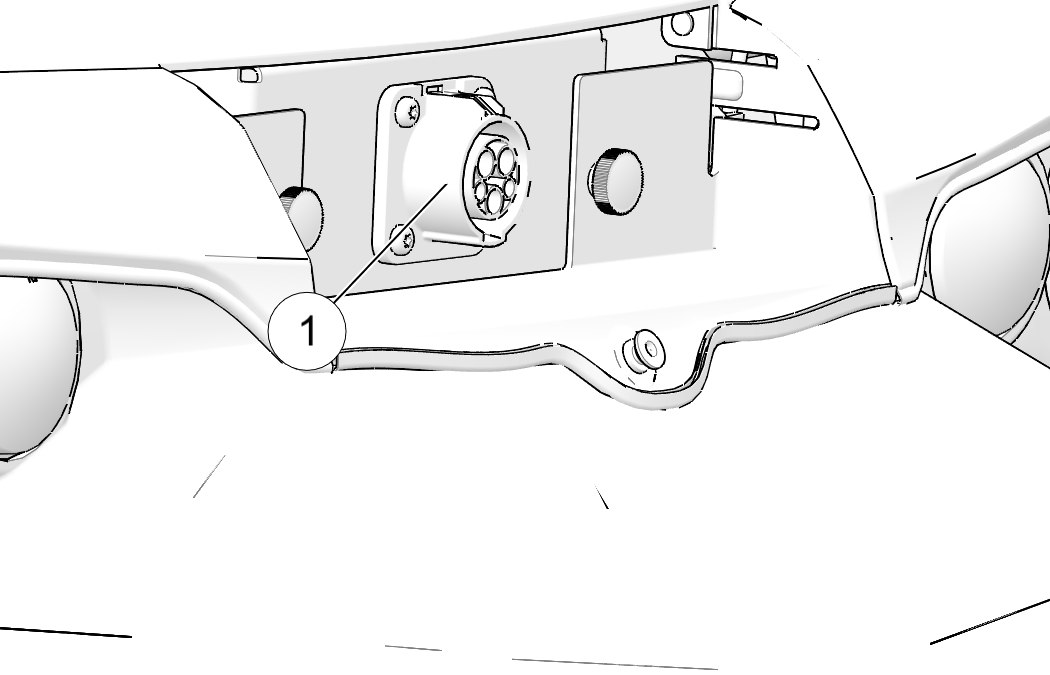
| NOTE |
| The standard charge receptacle is not compatible with J1772. |
The following
information applies to use of the standard charge receptacle. See Fast Charge Receptacle for information that applies to the use of the fast charge receptacle.
When charging the vehicle, always
use a standard 3-wire grounded extension cord of one of the following
types:
| TIP |
| A GFI (Ground Fault Interrupt) receptacle is recommended. See your authorized GEM dealer if you do not have a GFI receptacle at your regular recharge site. |
| NOTICE |
| Enhanced standard charge cord will not insert into the fast charge receptacle and damage may occur if forced. |
| NOTE |
| The following only applies to Flooded or AGM Batteries. Do not attempt to charge Li Ion batteries with a charger other than the one on-board the vehicle. |
| TIP |
| It is not necessary to remove or disconnect battery post connections during the alternate charging method. |
| Do not work in or near the battery compartment or on any other electrical
component of the vehicle while charging the batteries.
Before servicing the vehicle’s electrical system, always
disconnect the service disconnect first, then disconnect any electrical
accessory connections,
then disconnect the negative cable from the 12-volt battery, then
disconnect the negative terminal
from the main battery
pack. See Service Disconnect section in the Features and Control chapter
for more information. This
will disable the vehicle
by disconnecting the battery pack from the motor. It does not disable
the battery pack. HIGH VOLTAGE
will be present at
the battery terminals and contactor.
HIGH BATTERY VOLTAGE IS ALWAYS PRESENT. DO NOT TOUCH
THE BATTERY TERMINALS. |
| Always wear safety glasses or approved eye protection when servicing the vehicle. Wear a full-face shield and gloves when working with or around batteries and electrical connectors. |
| NOTICE |
| To avoid draining the battery system, always install an accessory exactly as stated in the provided installation instructions. |
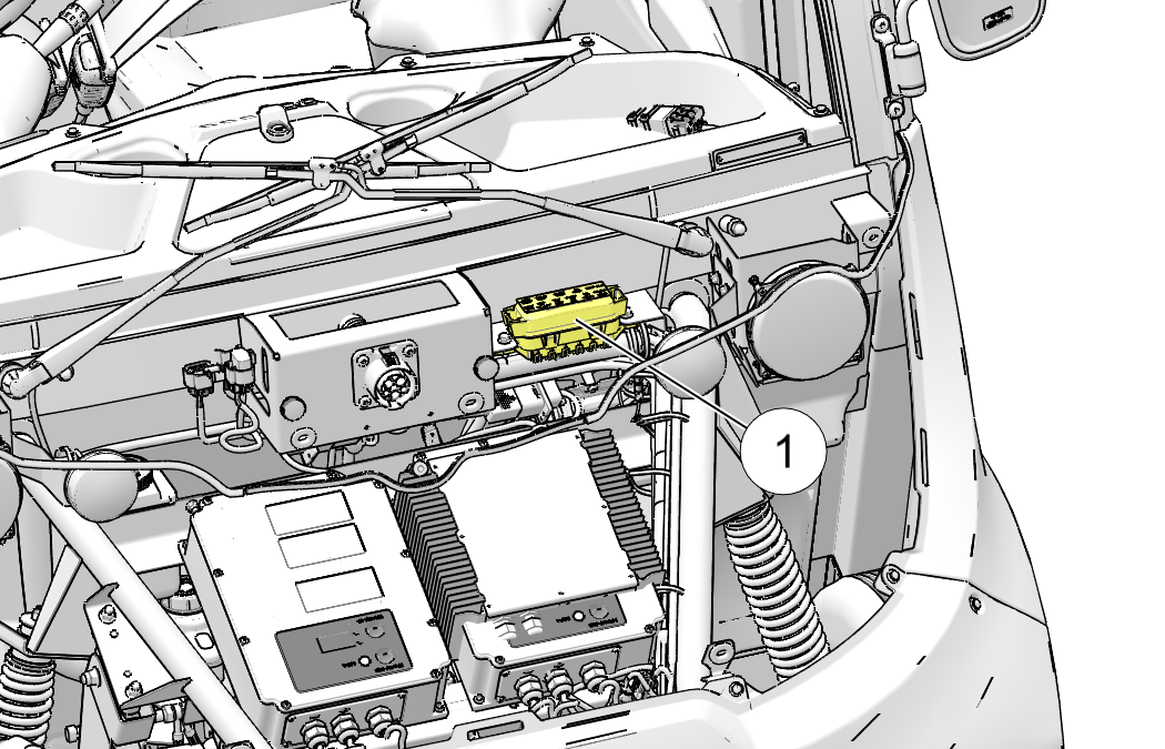
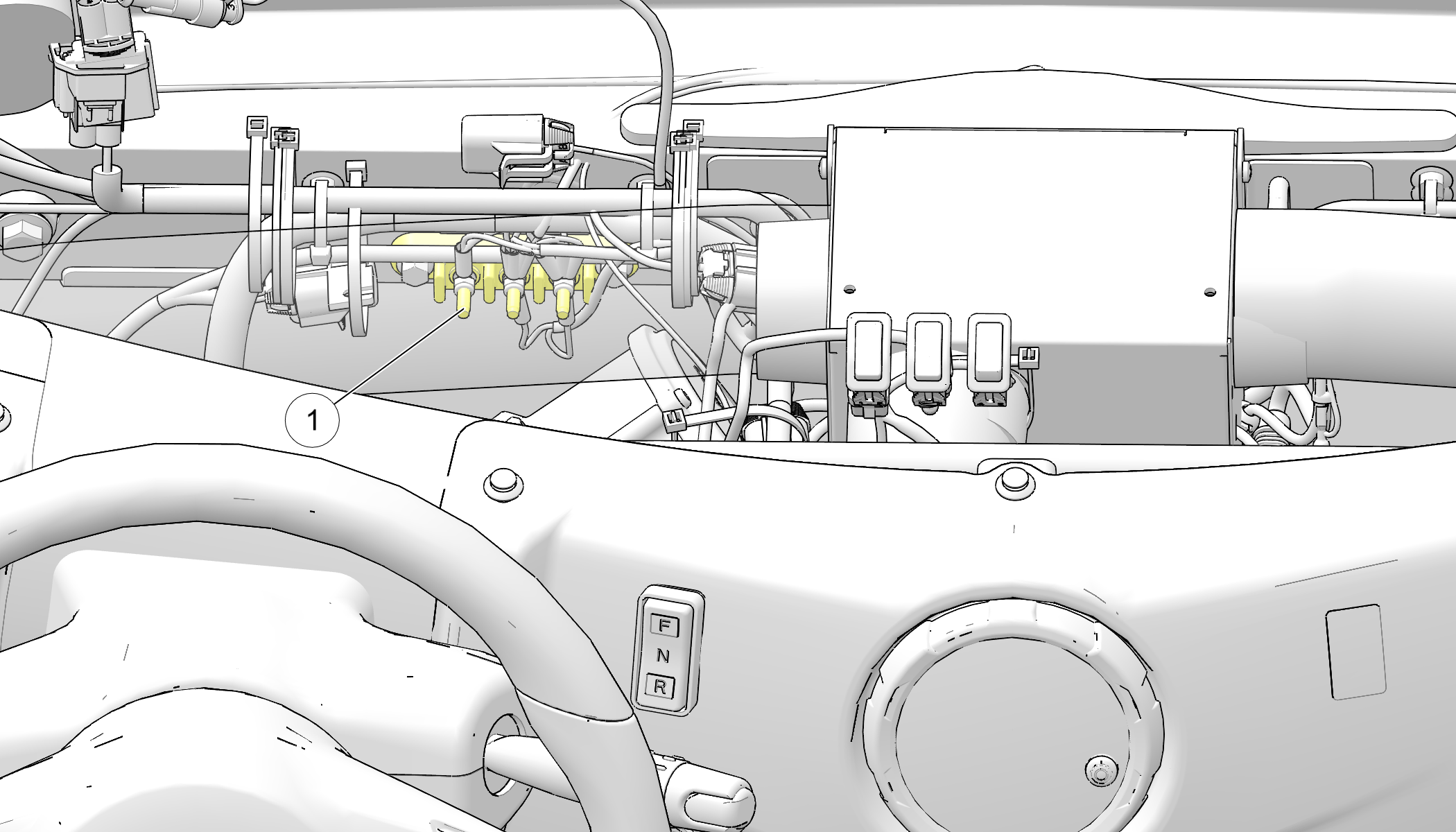
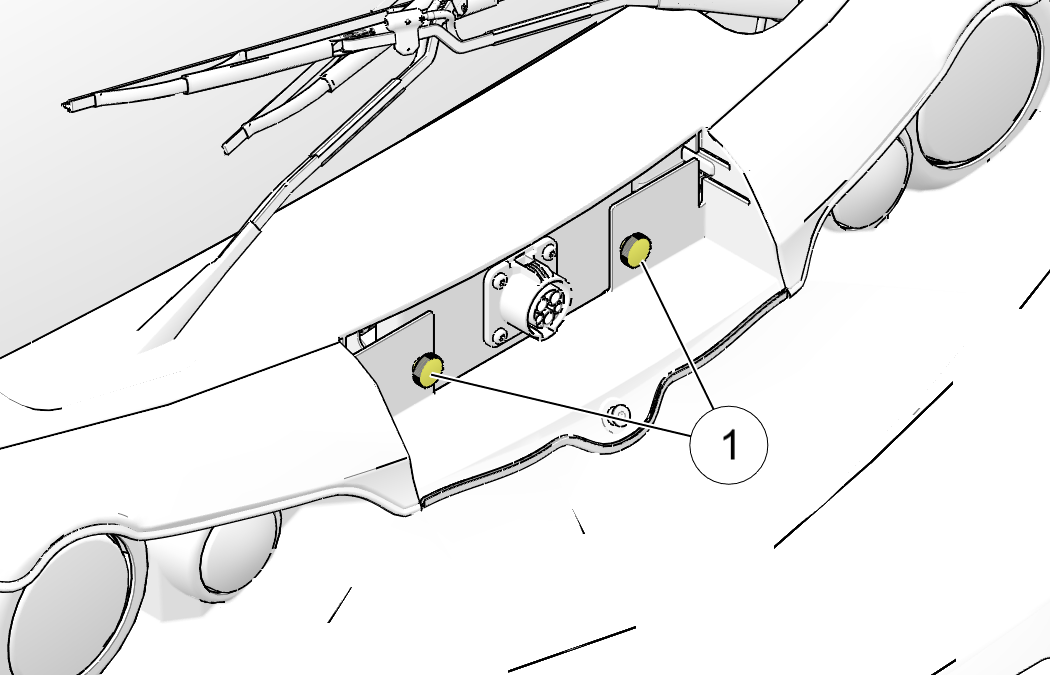
The fuse for the USB
port ![]() is located under the hood in the fuse block.
Always use fuses with the same type and rating.
is located under the hood in the fuse block.
Always use fuses with the same type and rating.
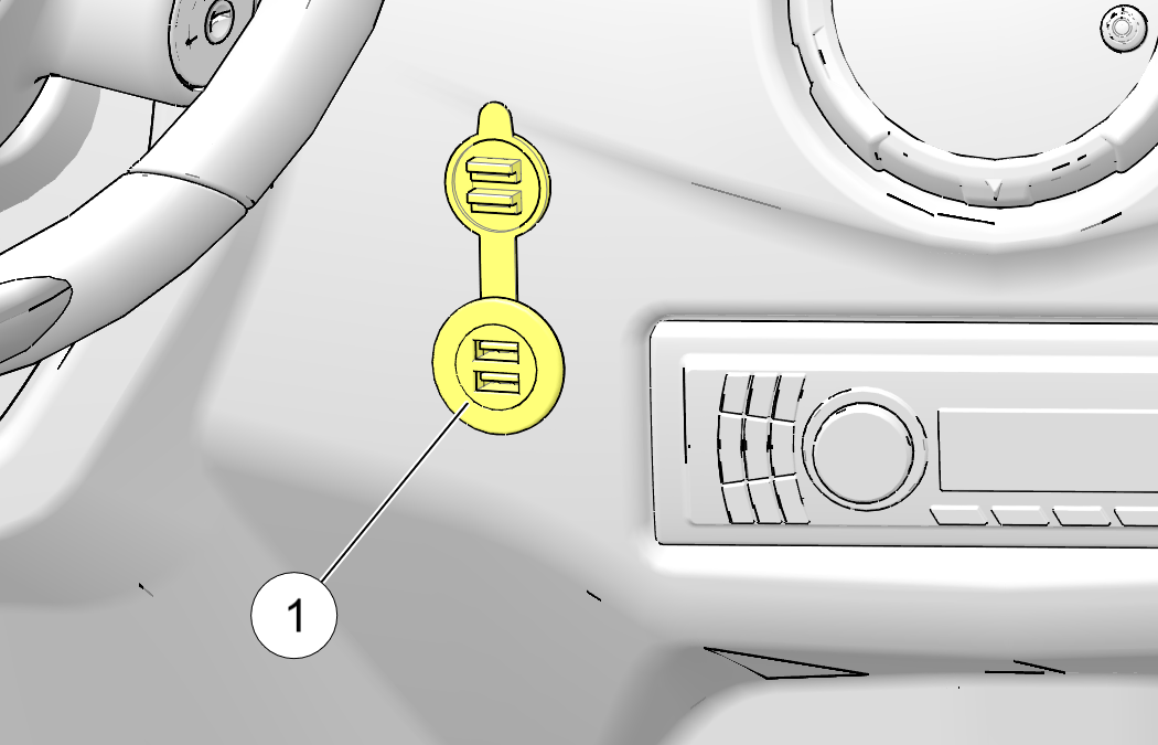
| NOTICE |
| Do not plug in devices requiring power exceeding 25 watts. Damage to the vehicle electrical system may occur or an accessory fuse may blow. |
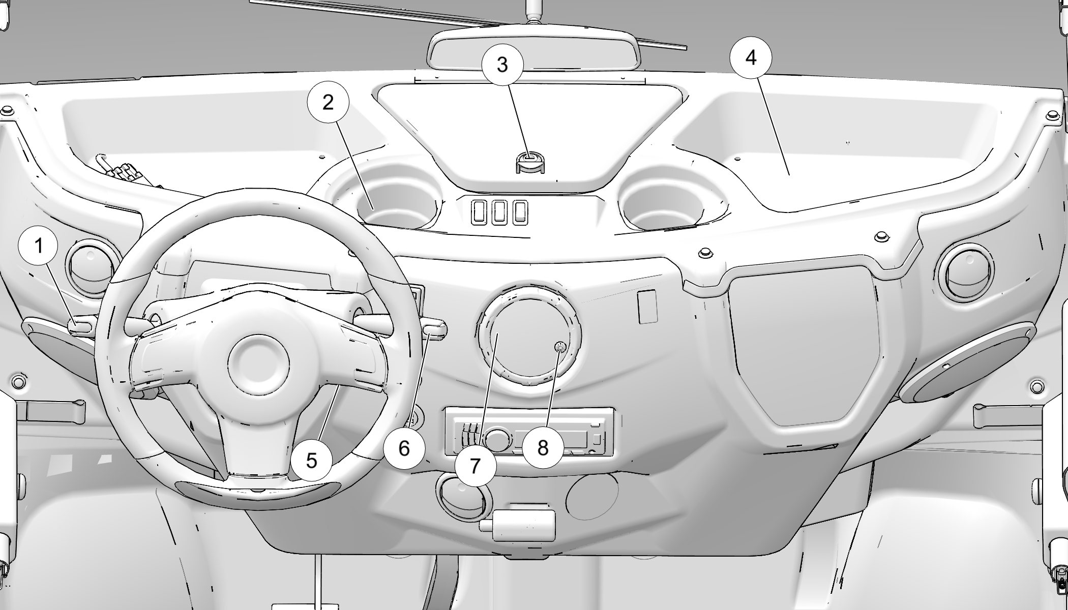
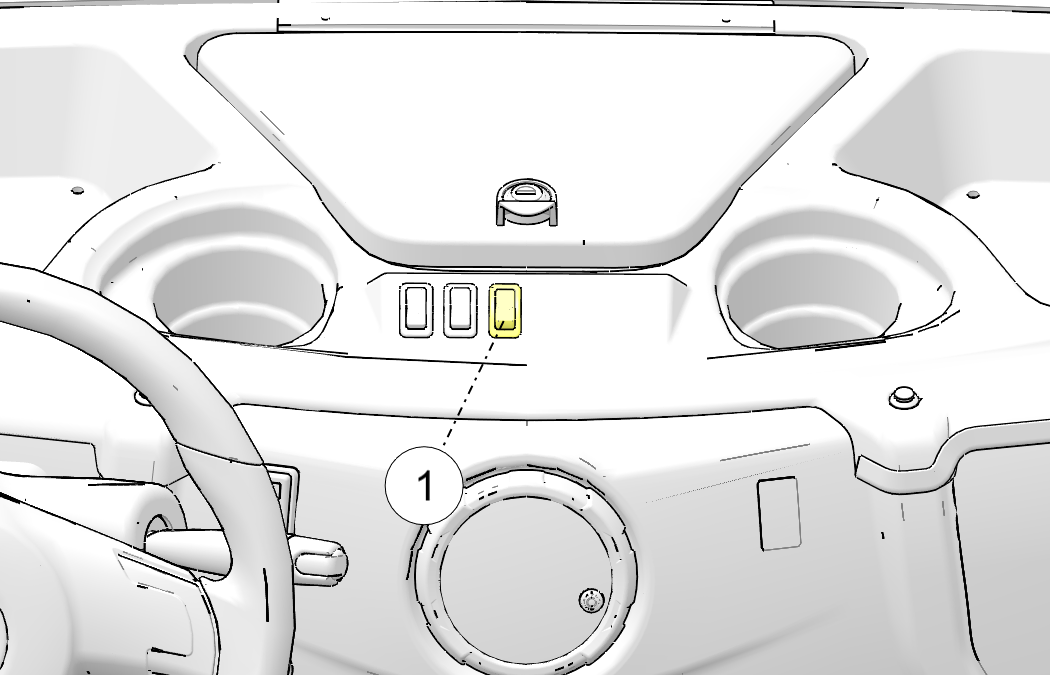
Turn the dome lights
on or off by pressing the switch located on the dash between cup holders. ![]()
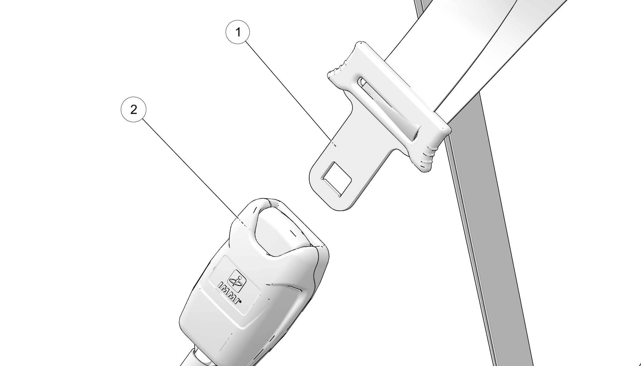
| Doors do not offer structural protection in the event of an accident and do not change the open body characteristics of the vehicle. The doors provide protection from the weather only. Always use seat belts. Failure to use the seat belts puts the driver and passengers at greater risk of serious injury or death in the event of an accident. |
| Always wear your seal belt. Ensure the seat belts are secured for operator and all passengers before operating. Failure to do so could result in the risk of serious injury or death. |
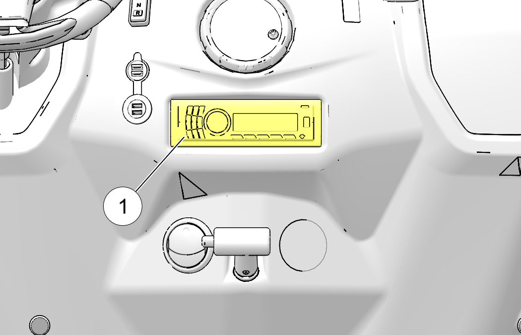
The optional stereo
system ![]() is mounted in the dash and features speakers,
FM radio, MP3 capabilities and Bluetooth functionality. Refer to your
stereo
system’s user manual for detailed operating instructions.
is mounted in the dash and features speakers,
FM radio, MP3 capabilities and Bluetooth functionality. Refer to your
stereo
system’s user manual for detailed operating instructions.
The optional solar
panel ![]() is mounted on top of the vehicle. Refer
to your solar panel user manual for details.
is mounted on top of the vehicle. Refer
to your solar panel user manual for details.
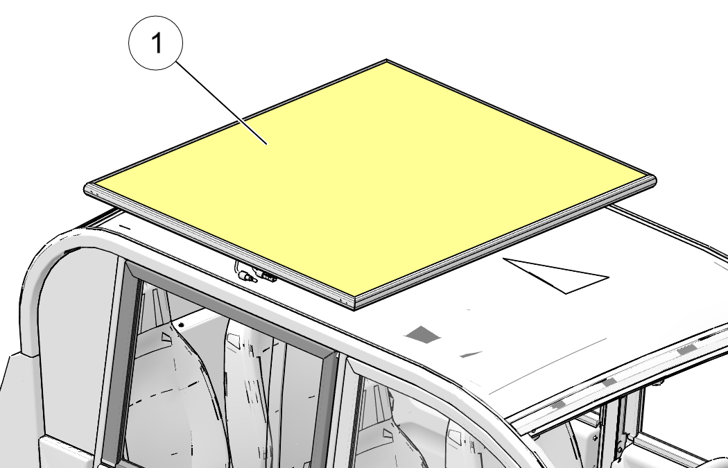
| Do not stack items on the solar panel. Never exceed the GVWR or GAWR. |
Cargo Carrier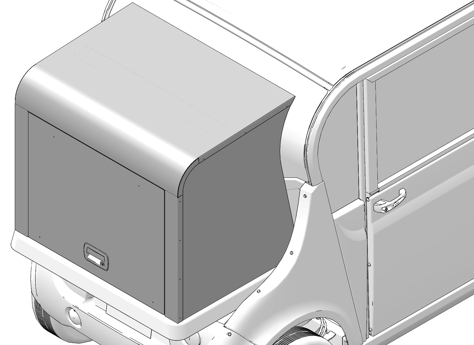
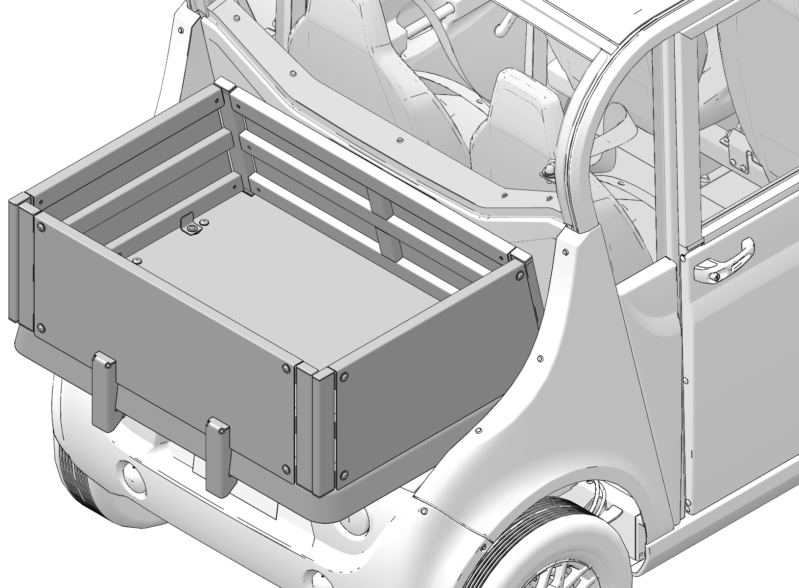
Linksback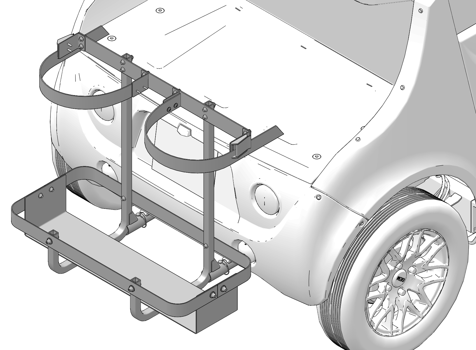
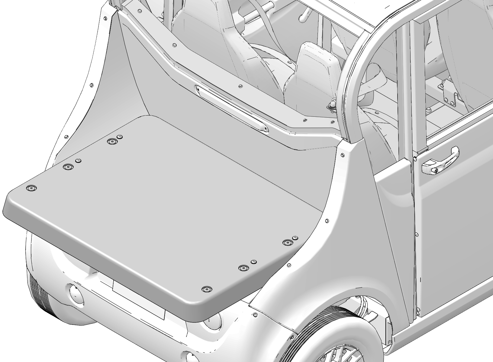
Stakeback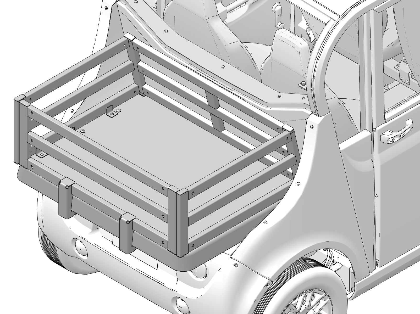
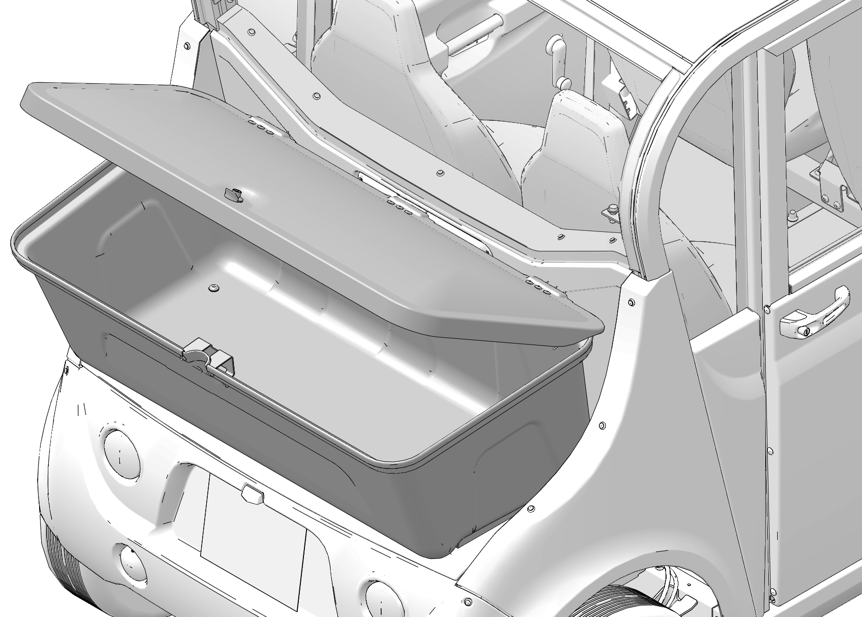
| Never carry a passenger on a rear accessory back. Do not overload an accessory back. Overloading the vehicle can reduce stability and handling and could cause loss of control. Never exceed the GVWR or the GAWR of the vehicle. See Gross Vehicle Weight Rating (GVWR). |
| NOTICE |
| Use only GEM-approved rear accessories. Others may cause damage to the locking system or vehicle, and may void warranty. |
| Never exceed the GVWR or the GAWR of the vehicle. See Gross Vehicle Weight Rating (GVWR). |
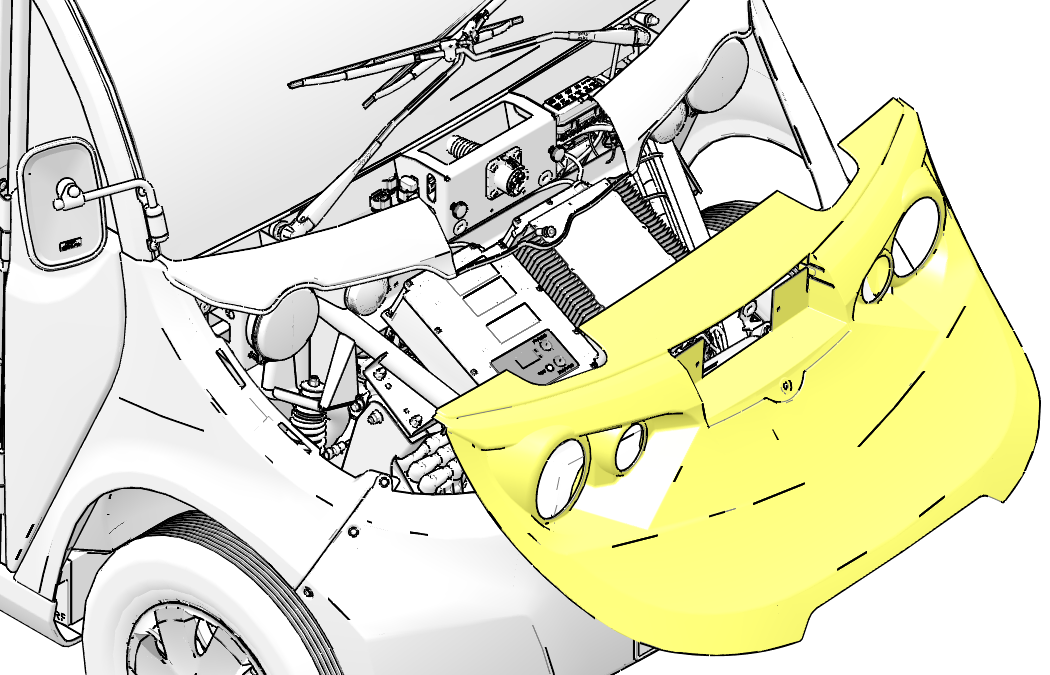
Front bumpers are for appearance only and will protect the body panels only from minor dents and scratches. They will not provide protection to the vehicle in front-end collisions.
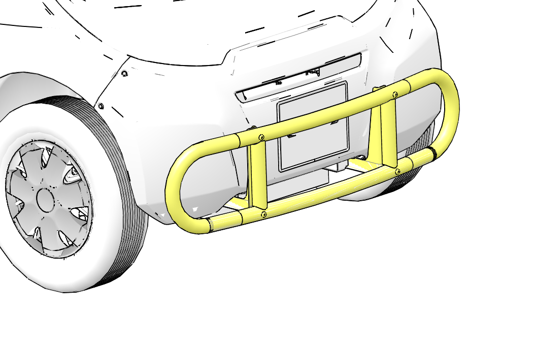
| NOTICE |
| Never use your GEM vehicle for pushing. Damage to the vehicle may result. |
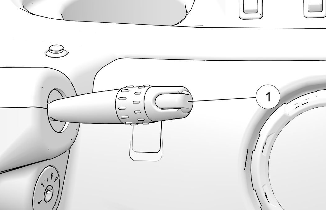
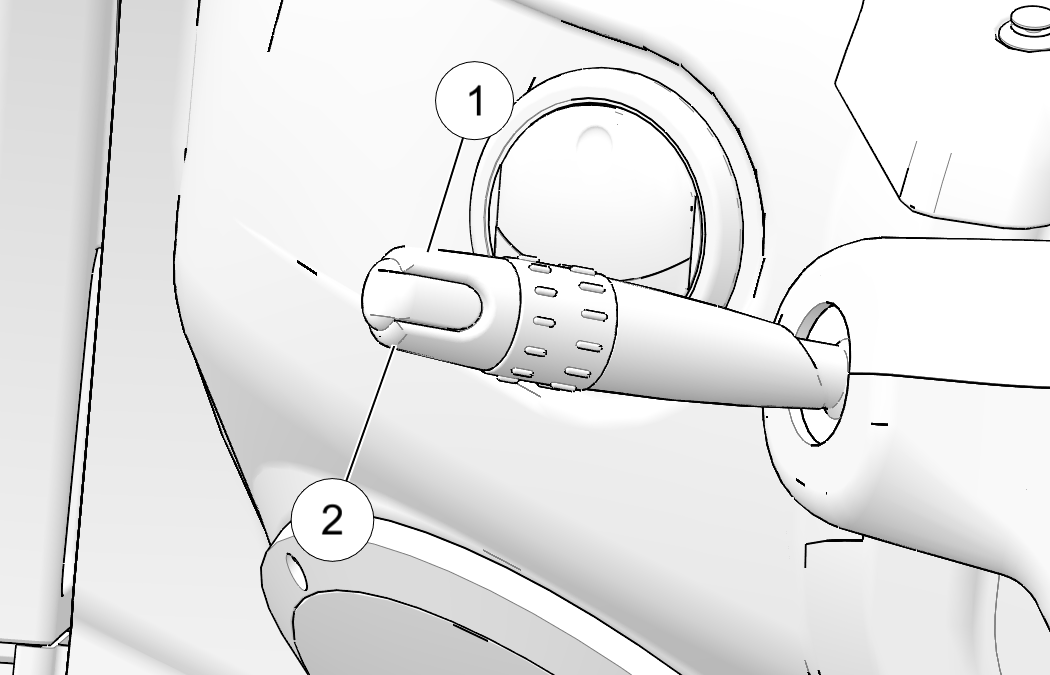
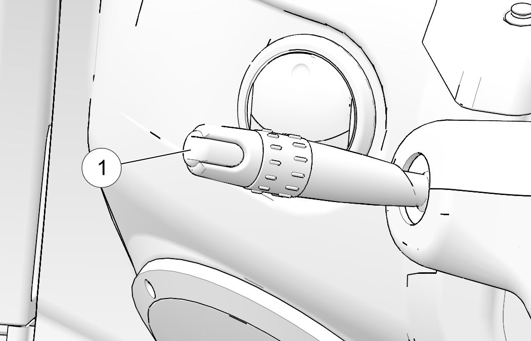
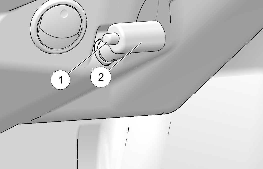
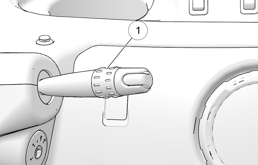
Rotate the knurled
barrel ![]() forward to turn the windshield wipers on.
forward to turn the windshield wipers on.
Pull the control lever toward the
driver’s seat to activate the washer. Check the washer reservoir fluid
level frequently.
When the level
is low, remove the cap and add windshield antifreeze (not radiator
antifreeze) rated for -25°F (-31°C). Operate
the system for a few seconds to flush out any residual
water.
| Commercial windshield washer solvents are flammable. Keep sparks, flames and cigarettes away. Handle with caution. |
© Copyright Polaris Industries Inc. All rights reserved.