
Content Source: 2019 Timbersled ST 93 Ripper Owner’s Manual (9928777 R03) > Installation Chapter
| IMPORTANT |
|
The Owner's Manual for this vehicle contains warnings, instructions and other information you must read and fully understand before safely riding or performing maintenance on this vehicle.Always follow the warnings and instructions in Owner's Manual. Click the CONTENTS link above for the Table Of Contents, or download a full PDF of the Owner Manual in the Owner Support area of Polaris.com |
| NOTE |
|
The disassembly process listed is universal for all bikes
using the ST 93 Ripper kit. This process may vary slightly between
makes and models.
Refer to your host bike’s owner’s manual for specific references and
disassembly procedures.
|
| NOTE |
|
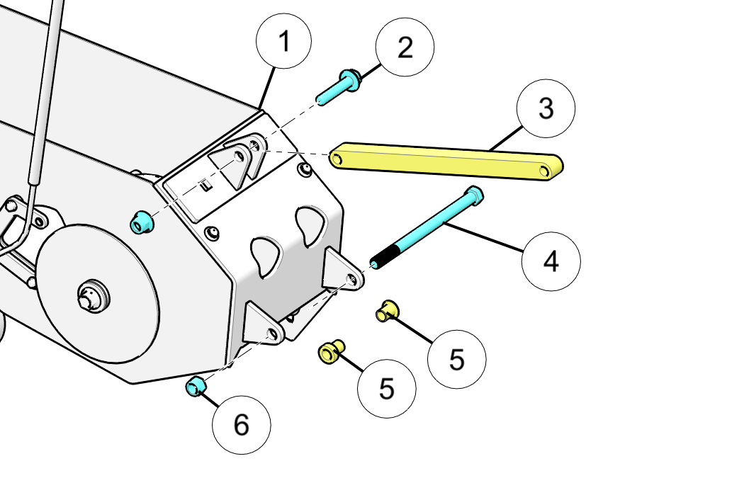
Keep upper shock bolt for later use as this item will be reinstalled. |
| NOTE |
|
It is recommended to cable tie all bushings, spacers, etc. to their corresponding parts at all pivoting points to prevent losing any parts during storage. |
| NOTE |
|
Keep front axle bolt for later use, this item will be reinstalled. |
|
Left Side |
Right side |
|||
|
Spacer Spec. |
Part # |
Spacer Spec. |
Part # |
|
|
Honda |
0.80 mm |
5141218 |
6.87 mm |
5141219 |
|
Kawasaki |
N/A |
N/A |
N/A |
N/A |
|
Yamaha |
N/A |
N/A |
15 mm |
5141220 |
|
*Left and Right as positioned sitting on the bike |
||||
| NOTE |
|
Kawasaki KLX models do not require any spacers. Honda CRF models require left and right swing arm bolt spacers/reducers. Yamaha TTR models require a single spacer positioned on the right side of the bike. |
| TORQUE | |
|
54 Nm (40 Ft. Lbs) |
| NOTE |
|
KAWASAKI MODELS ONLY skip Step 4 and complete Steps 5 and 6. For Honda and Yamaha models continue with Step 4. |
| TORQUE | |
|
60 Nm (44 Ft. Lbs) |
| NOTE |
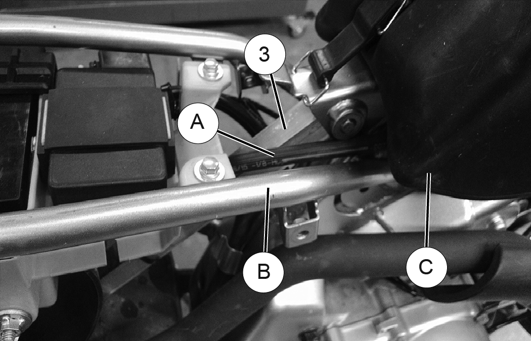
|
This step includes the upper strut rod installation and brake line routing for Kawasaki models only. |
| NOTE |
|
Some Kawasaki models can use secondary bolt hole in the strut rod for lower ride height. |
Bolt in place using the original upper strut rod bolt or pin and torque to the bike manufacturer’s specifications. Once you have the upper portion of the strut rod in place, torque the lower portion of the strut rod to the specification listed below.
| TORQUE | |
|
60 Nm (44 Ft. Lbs) |
|
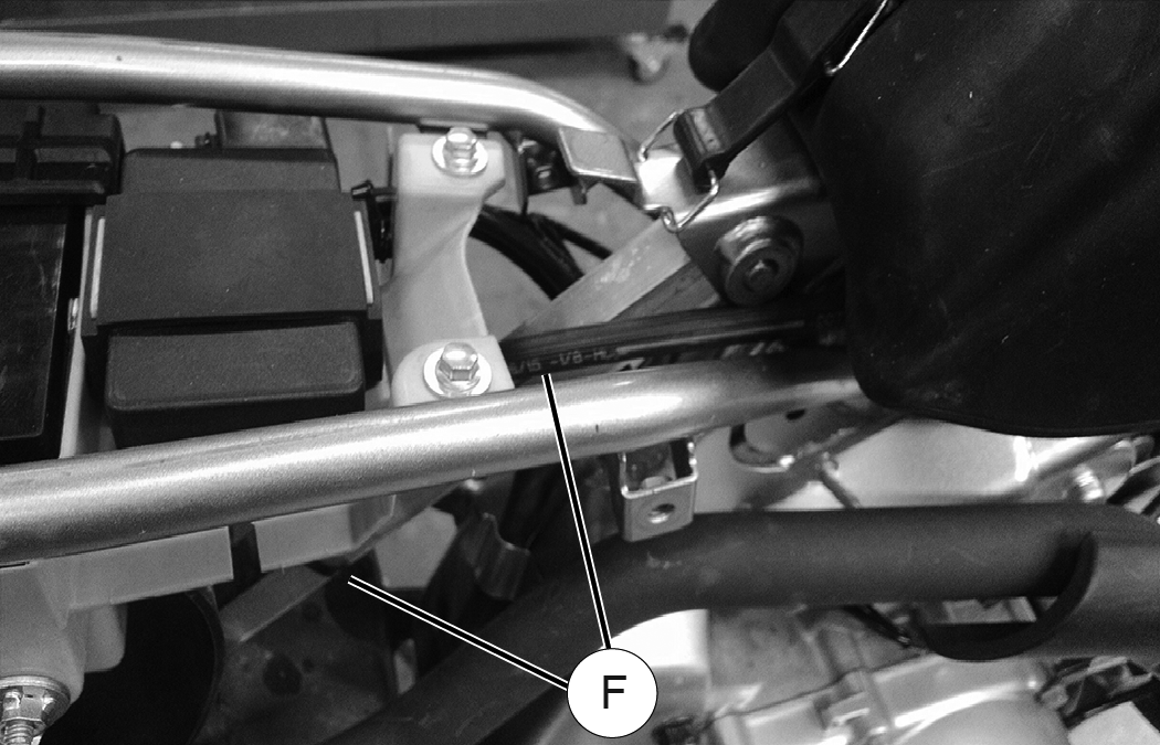
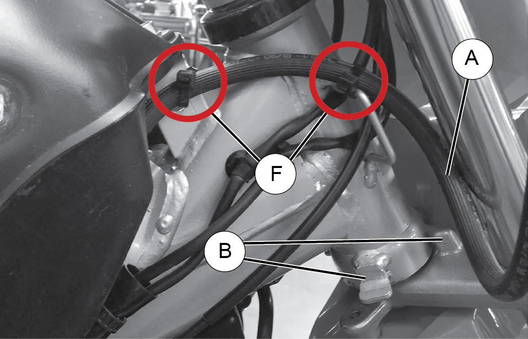
When routing brake lines it is critical that you keep all brake lines away from any surfaces, such as engine or exhaust, that can become hot while operating the vehicle. Failure to comply will adversely affect the vehicles brake system and may lead to severe injury or death. |
|
When routing brake lines, make sure
there is a minimum of one inch of clearance between the brake line |
|
When routing brake lines it is critical that you keep
all brake lines away from any surfaces, such as engine or exhaust,
that
can become hot while
operating the vehicle. Failure to comply will adversely affect the
vehicles brake system and may lead
to severe injury or death.
|
| NOTE |
|
Refer to images of Honda model for routing references. |
|
When routing brake lines, make sure
there is a minimum of one inch of clearance between the brake line |
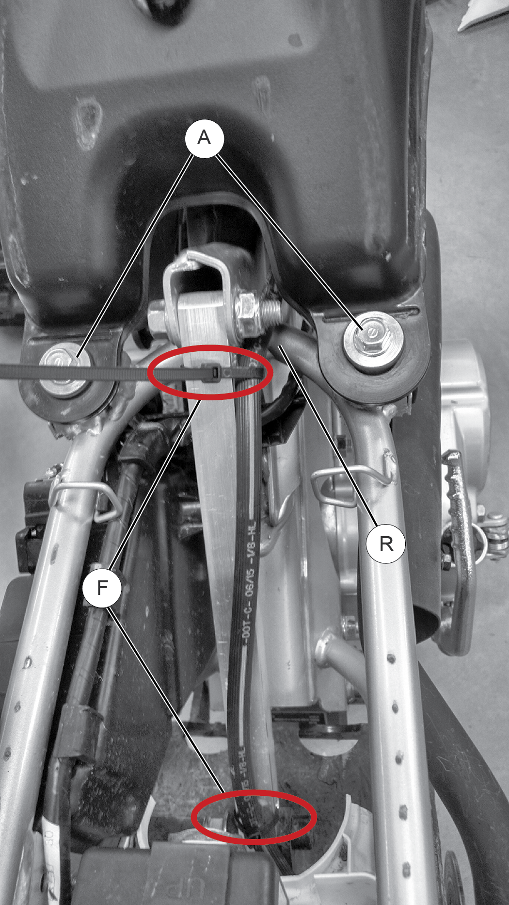
|
When routing brake lines, make sure
there is a minimum of one inch of clearance between the brake line |
| NOTE |
|
Reference you host bikes owner’s manual or manufacturers specifications for proper torque specifications. |
| TORQUE | |
|
25 Nm (18 Ft. Lbs) |
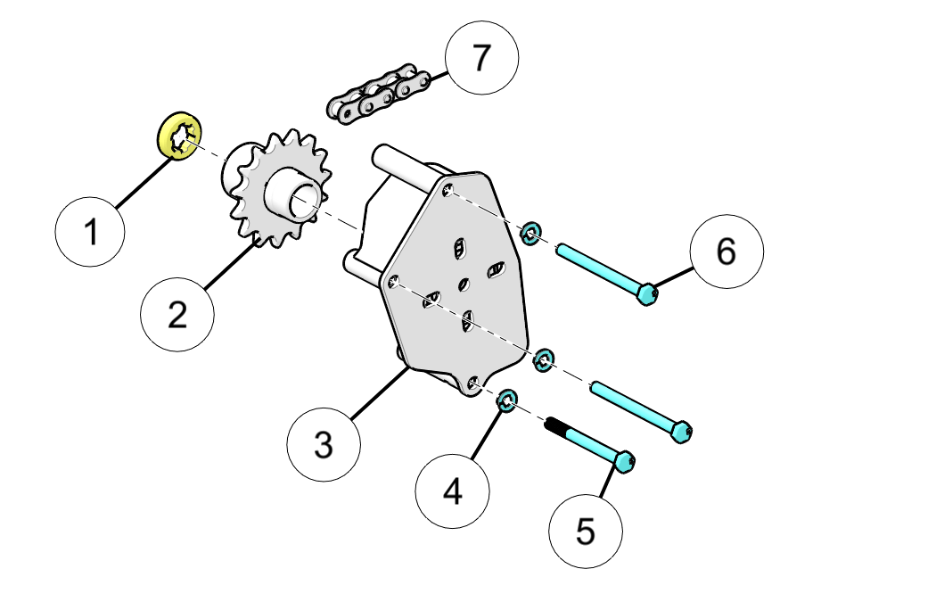
| NOTE |
|
Chain will stretch within the first 5hrs. You will want to check for proper chain tension. Chain slider is not intended to roll and can be rotated as needed to keep proper chain tension on usable surface of slider. |
|
Left Side |
Right side |
|||
|
RDCR Spec. |
Part # |
RDCR Spec. |
Part # |
|
|
Honda |
18.03 mm |
5141390 |
25.4 mm |
5141389 |
|
Kawasaki |
17.35 mm |
5141392 |
17.35 mm |
5141392 |
|
Yamaha |
14.91 mm |
5141394 |
20.49 mm |
5141393 |
|
*Left and Right as positioned sitting on the bike |
||||
 Apply nut
 | TORQUE | |
|
45 Nm (33 Ft. Lbs) |
|
Failure to torque fasteners as directed will adversely affect the steering system and may lead to severe injury or death. |
 For now, just
snug the front axle bolt, do not tighten until after step 6.
For now, just
snug the front axle bolt, do not tighten until after step 6. Using Qty.–2,
M8 x 75mm bolts
Using Qty.–2,
M8 x 75mm bolts | TORQUE | |
|
20 Nm (15 Ft. Lbs) |
| IMPORTANT |
|
Refer to manufacturers specifications for proper torque setting. |

| NOTE |
|
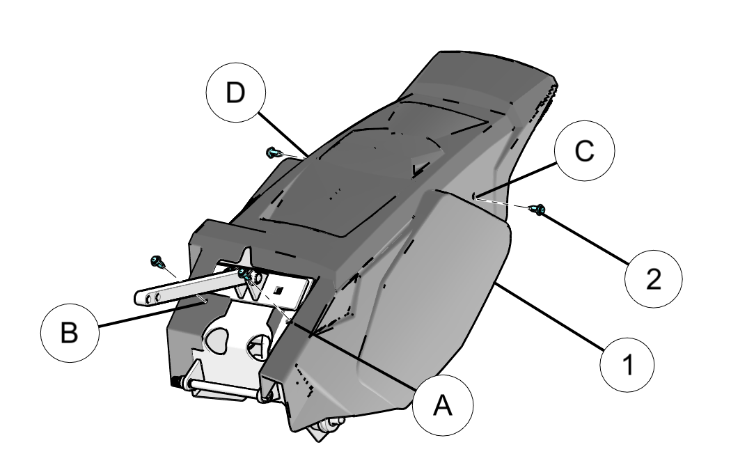
The rear cowling is pliable, the easiest process for lining up the rear fastener mounting holes of the skid frame with the cowling holes is to pull out on the bottom most part of the cowling in the middle of the molding. This will pull the rear hole in the cowling forward allowing you to line up the holes to insert the nylon rivet fastener. |
© Copyright Polaris Industries Inc. All rights reserved.